I give up, we're going round in circles.
You may be, I'm not.
I've just given the reasons behind the reverse return and the LLH.
Sorry if you don't like it.

I give up, we're going round in circles.
I give up, we're going round in circles.
You may be, I'm not.
I've just given the reasons behind the reverse return and the LLH.
Sorry if you don't like it.


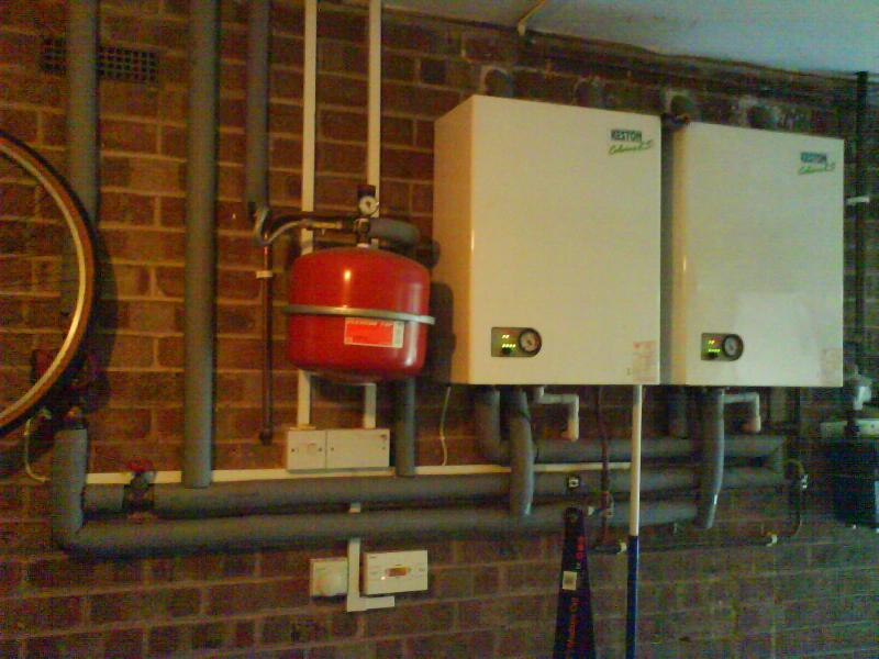
Been reading the MI on some of the Keston, and I'm pretty sure they wouldn't approve the two boiler, reverse return system.
Perhaps if I'm bored tomorrow I'll send them an e.
Been reading the MI on some of the Keston, and I'm pretty sure they wouldn't approve the two boiler, reverse return system.
Perhaps if I'm bored tomorrow I'll send them an e.
I think they might approve it.
http://www.keston.co.uk/downloads/support_info/multiple/2xcelsius-v2.pdf[/QUOTE]
Oh dear whats that ABV doing there.
The rest is just about spot on to what I've spent the last 7 pages saying.
Oh dear whats that ABV doing there.
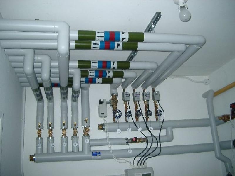
Should I consider getting a magnaclean filter installed on my fragile dual Keston Celsius 25 system? If so, where? As it is primarily to protect the boilers, my initial thought is it should be in the low-loss header between the primary return and the boilers, maybe on the far right of the picture, next to the gas meter, so it is immediately before the boiler returns.
I don't understand why there is a 3-port valve for a single zone CH and DHW when there is a 2-port valve on the DHW by the cylinder, unless it's left over from the previous installation (single 25kW non-condensing with vented indirect DHW).
Oh dear whats that ABV doing there.
Since it's not a LLH system, it is intended to maintain the flow through the boiler if the TRVs are shut. I've no issues with the ABV, you just don't need it with the LLh arrangement.
I think there will be very little (no) flow through the radiators as 99% of the boiler flow would go through the short circuit gate valve. Isn't that what happens with a LLH if there is no secondary circulation pump?What happens if you replace the ABV with a fully open gate valve as in the OP's pic.
My temperature measurement chart suggests the flow through the boilers is more than adequate (maximum boiler delta-T of 15°C).
It looks like the primary circuit should be 35mm instead of 28mm. So doitall suggests 42mm, fair play.
If you need to find a tradesperson to get your job done, please try our local search below, or if you are doing it yourself you can find suppliers local to you.
Select the supplier or trade you require, enter your location to begin your search.
Are you a trade or supplier? You can create your listing free at DIYnot Local