Manrose Fan with timer and shutters

Joined
20 Jan 2012
Messages
160
Reaction score
4
Location
Norwich
Country
United Kingdom
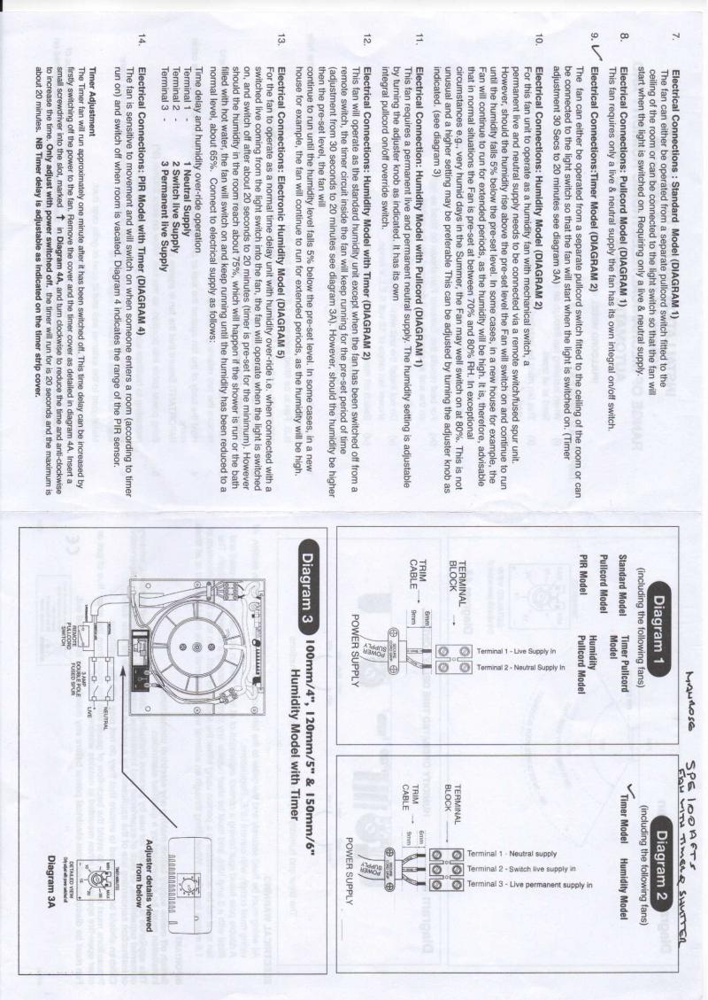
I am replaclng a ceiling fan with a Manrose Fan with timer and shutters.

Model Manrose SPE100AFTS double insulated no earth connection required.

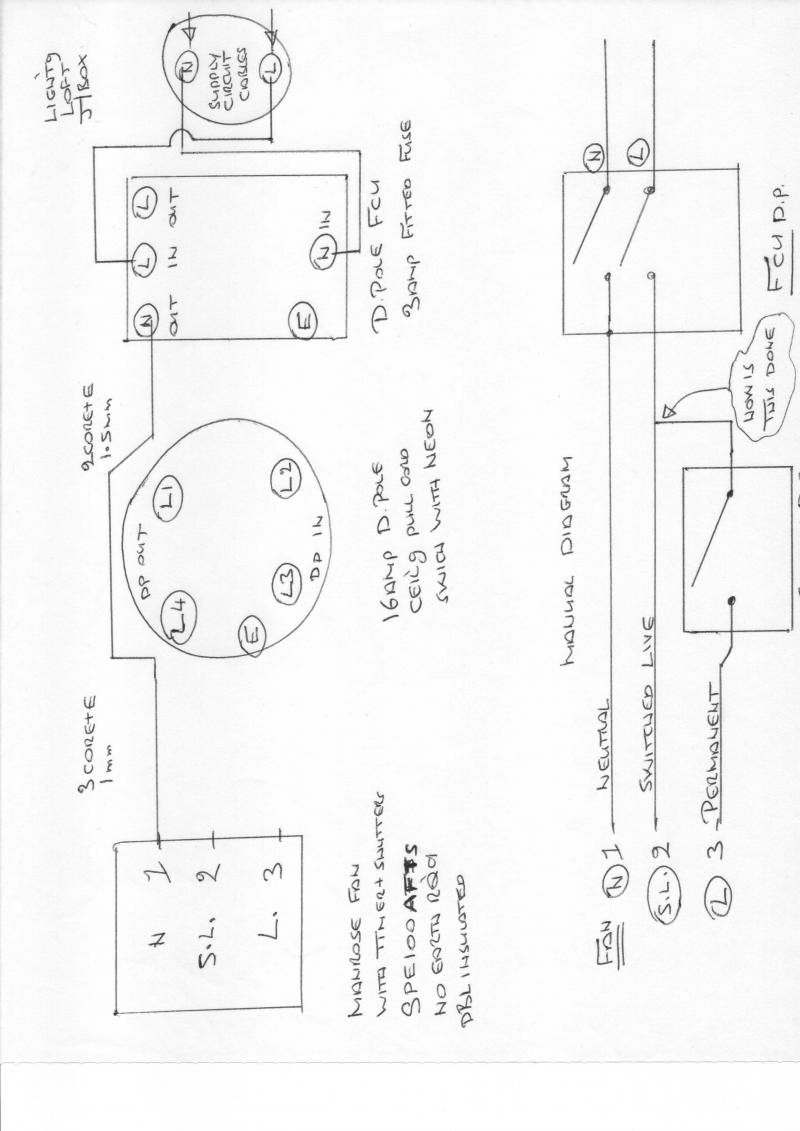
I want to use a lighting circuit junction box in the loft for supply.

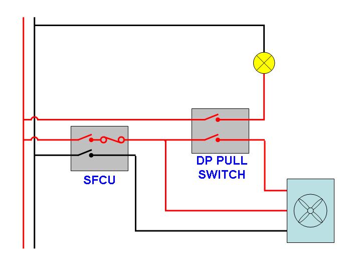
I want to use the existing Double Pole 16 amp ceiling pull switch for the switch.

I want to use a Double Pole FCU with 3 amp fuse fitted.

The diagrams show terminal positions of each item; Fan, Switch, FCU, Junction box.

Questions:

How should this be wired to show the Neon indicator lit only when switch is ON.

In simple terms; which wire goes to which terminal; a diagram would be appreciated a picture is worth a thousand words.

I have wired the circuit successfully and the fan works ON/OFF OK but...the timer does not operate; hence the wiring is not correct.

Thank you
 
Sponsored Links
So it's not linked to the light switch?
You want to turn the fan on with the 16a pull ?

You 16a is double poll So your probably removing the neutral to the fan so the over run timer can't work.

Try linking the neutrals together at the pull
 
Well you live needs to go straight from fcu to fan along with the neutral.

The pull switch connects from fcu L to fan SL.

You will need a neutral wire there if u want the neon to work.
 
Sponsored Links
If you don't want it on with the light you don't need a double pole switch.

This is the normal way - with light.

fanwiring7ib.jpg
 
some of the blank bits filled in !


Just need to understand what L1, L2, L3, L4 are on the switch.

i.e Lin Lout Nin Nout

THe switch instructions should help but someone should know.


In practical cable routing terms, you should run 2C+E between the FCU and pull switch.

And 3C+E between the pull switch and fan.

The neutrals should be connect to the same terminal at the switch to allow the timer and neon to work.

--------------------------------------------

In practical cable routing terms, you should run 2C+E between the FCU and pull switch

ANSWER 1.5mm 2C+E is from Junction box to FCU, then 1.5mm 2C+E is from FCU to Switch and 3C+E is from Switch to Fan.

Just need to understand what L1, L2, L3, L4 are on the switch.

ANSWER L1 is marked "COM 2 Way" the others; L2 L3 L4 have no other markings
 
AndyPRK";p="3111003 said:
So it's not linked to the light switch?
You want to turn the fan on with the 16a pull ?

You 16a is double poll So your probably removing the neutral to the fan so the over run timer can't work.

So it's not linked to the light switch?

ANSWER No, my reason for this is that I don't want the light on in the daytime; this was the existing setup not connected via light and the existing setup was switch wired to Junction Box, then Junction Box direct via 3C+E to Fan using the same DP switch.
 
I guess you need to use a meter to work out what connections are what on the switch, if you are sure you have the correct switch type.
 

DIYnot Local

Staff member

If you need to find a tradesperson to get your job done, please try our local search below, or if you are doing it yourself you can find suppliers local to you.

Select the supplier or trade you require, enter your location to begin your search.


Are you a trade or supplier? You can create your listing free at DIYnot Local

 
Sponsored Links
Back
Top