
- Joined
- 11 Jan 2004
- Messages
- 46,718
- Reaction score
- 3,929
- Country

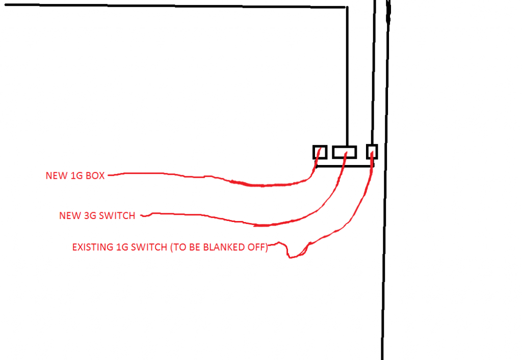
Need a 3G grid with 25mm k/o's. Anyone know of any?
Failing that, could I convert a horizontal 25mm conduit supplying the cables to this switch into 2x 20mm drops?
Ta.
Forget this, I'd forgotten about these. http://www.tlc-direct.co.uk/Products/MTRED25slash20.html

Failing that, could I convert a horizontal 25mm conduit supplying the cables to this switch into 2x 20mm drops?
Ta.
Forget this, I'd forgotten about these. http://www.tlc-direct.co.uk/Products/MTRED25slash20.html

")