Need help understanding my S-Plan Wiring

Joined
20 Oct 2017
Messages
11
Reaction score
0
Country
United Kingdom
Hi,

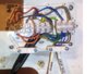
I recently re-terminated my S-Plan central heating wiring into a new junction box to tidy things up and also to try to understand how it was wired originally before I moved into the property.

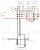
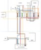
I have created a diagram of the current wiring and even though the central heating is working (although not 100% correctly as the HW must be on for the CH to work).

Upon comparing this to the standard S-Plan wiring diagrams online. I have concluded that the current wiring is incorrect, and that an additional cable would need running from the junction box to the boiler to correct it.

One thing that I cannot understand however is where the wires from the room thermostat terminate?

In the diagram I have joined them to the CH and HW red / yellow cables that go from the programmer to the junction box (as I cannot locate where the red / yellow cables from the room thermostat connect into the system).

To confirm the CH zone valve does close when the termostat reaches it's desired temperature which means it must be getting a signal from the room thermostat but with only one set of red / yellow wires in the junction box and with those going to the programmer i can't understand how.

Has anyone seen an similar setup that can offer an explanation ?

Thanks in Advance.
 

Attachments

  • Splanwiring.jpg
    Splanwiring.jpg
    73.6 KB · Views: 16,458
Sponsored Links
One thing that I cannot understand however is where the wires from the room thermostat terminate?
Actually from your diagram, there are a lot of things you don't understand, however to answer your question:

The room stat should get its live supply from the programmer heating on connection (4). In turn when the thermostat calls for heat (on) then the switched live output connection goes to the heating motorised valve to operate its motor to wind it open and hold it in the open position. [When the live is removed from the valve a spring pulls it back to the closed position and it can usually be heard whirring.]

Once the heating motorised valve is open the internal microswitch (orange & grey wires) provides control of the boiler.

Your wiring diagram contains many errors, the most obvious at a quick glance are:

The room stat is connected to the hot water on (programmer terminal 3) and heating on (programmer terminal 4) at the programmer
The cylinder thermostat is wired directly to the motorised valve boiler control and not the motorised valve motor.
The room stat is not wired in circuit as the heating on (programmer 4) goes directly to the motorised valve so effectively the thermostat is bypassed.

There is a handy diagram here that you can click on to see the various 'states of the S-Plan to see what should happen and when.
 
Last edited:
Actually from your diagram, there are a lot of things you don't understand, however to answer your question:

The room stat should get its live supply from the programmer heating on connection (4). In turn when the thermostat calls for heat (on) then the switched live output connection goes to the heating motorised valve to operate its motor to wind it open and hold it in the open position. [When the live is removed from the valve a spring pulls it back to the closed position and it can usually be heard whirring.]

Once the heating motorised valve is open the internal microswitch (orange & grey wires) provides control of the boiler.

Your wiring diagram contains many errors, the most obvious at a quick glance are:

The room stat is connected to the hot water on (programmer terminal 3) and heating on (programmer terminal 4) at the programmer
The cylinder thermostat is wired directly to the motorised valve boiler control and not the motorised valve motor.
The room stat is not wired in circuit as the heating on (programmer 4) goes directly to the motorised valve so effectively the thermostat is bypassed.

There is a handy diagram here that you can click on to see the various 'states of the S-Plan to see what should happen and when.

Hi Stem,

Thanks for the quick reply. Unfortunately I have inherited the current setup and in order to correct it I would like to first fully understand the current wiring.

In other standard S-Plan wiring diagrams the room thermostats red / yellow wires run to terminals 4 and 5 in the junction box respectably, whereas I seem to have less wires than this with only one set of red / yellow wires in the junction box that go to the programmers 3 and 4 terminals.

As stated, in the diagram only I have joined the red / yellow wires that go from the thermostat to the others but in reality I do not exactly know where the room stat wires terminate as they are not in the junction box or programmer. However the CH valve does close when the thermostat reaches it's set temperature i.e. not constantly open.

Just to Clarify here is how everything works currently.

HW on - Boiler, Pump and HW Valve receive power and the boiler / pump run until the Cylinder stat reaches it's set temperature.

HW and CH on - Boiler, Pump and HW/CH Valves receive power. Valves open / close based on their set max temperatures independently and the boiler / pump stop when there is no call from either thermostat.

CH does not work independently and there is no pump over-run which are things that need fixing but not the reason for this post.

Hopefully someone has a seen a setup similar to this and understands the lack of additional wires i was expecting in the junction box.

Thanks
 
Last edited:
Sponsored Links
The wiring diagram you have produced is wrong on so many levels, it just won't work. Every component (with the possible exception of the boiler and pump) is incorrectly connected in some way. It would take pages of writing to try to explain what is wrong. Because so much of the wiring is incorrect, there's no point in understanding what is wrong, you need to understand how it should be done.

I sent you a link to an animated wiring diagram to show how it is wired previously. I can't really give you much more help than that. Don't get hung up on the colours of the wires used for interconnecting cables and which terminal is used for what at the wiring centre, because not all installers use the same wire colours or terminal layout, and not all thermostats and programmers have the same terminal markings. What won't change is how they are all connected to each other, and work together. So:

HOT WATER
Programmer terminal 'hot water on' (usually terminal 3)------> Cylinder thermostat (Live) [your diagram shows it connected to the room stat and valve orange wires, both of which are wrong]
Cylinder thermostat (switched Live)-----> Hot water motorised valve Live (brown wire)

HEATING
Programmer terminal 'heating on' (usually terminal 4)-----> Room thermostat (Live) [your diagram also shows it going to the CH motorised valve brown wire which is wrong]
Room thermostat (Switched Live)-----> Heating motorised valve Live (brown wire)

BOILER & PUMP CONTROL
Both motorised valve grey wires connect to a permanent live (ie one from the main 3A fused 230V supply and not one switched by the programmer or a thermostat)
Both motorised valve orange wires go to the boiler & pump* switched live.
[Note: Your diagram has grey & orange wired the opposite way around. For the purpose of operation it is OK, but it doesn't follow convention]

The programmer / some room thermostats (depends on the type) / motorised valves / boiler will also require a neutral connection.
Earths connected to earth as applicable.

If you can't follow and understand the diagram below you should really get a professional in who does to wire it up for you.

S-Plan-Wiring.gif


*If the boiler has dedicated terminals marked for connection of the pump, the pump should be wired to them instead.
 
The wiring diagram you have produced is wrong on so many levels, it just won't work. Every component (with the possible exception of the boiler and pump) is incorrectly connected in some way. It would take pages of writing to try to explain what is wrong. Because so much of the wiring is incorrect, there's no point in understanding what is wrong, you need to understand how it should be done.

I sent you a link to an animated wiring diagram to show how it is wired previously. I can't really give you much more help than that. Don't get hung up on the colours of the wires used for interconnecting cables and which terminal is used for what at the wiring centre, because not all installers use the same wire colours or terminal layout, and not all thermostats and programmers have the same terminal markings. What won't change is how they are all connected to each other, and work together. So:

HOT WATER
Programmer terminal 'hot water on' (usually terminal 3)------> Cylinder thermostat (Live) [your diagram shows it connected to the room stat and valve orange wires, both of which are wrong]
Cylinder thermostat (switched Live)-----> Hot water motorised valve Live (brown wire)

HEATING
Programmer terminal 'heating on' (usually terminal 4)-----> Room thermostat (Live) [your diagram also shows it going to the CH motorised valve brown wire which is wrong]
Room thermostat (Switched Live)-----> Heating motorised valve Live (brown wire)

BOILER & PUMP CONTROL
Both motorised valve grey wires connect to a permanent live (ie one from the main 3A fused 230V supply and not one switched by the programmer or a thermostat)
Both motorised valve orange wires go to the boiler & pump* switched live.
[Note: Your diagram has grey & orange wired the opposite way around. For the purpose of operation it is OK, but it doesn't follow convention]

The programmer / some room thermostats (depends on the type) / motorised valves / boiler will also require a neutral connection.
Earths connected to earth as applicable.

If you can't follow and understand the diagram below you should really get a professional in who does to wire it up for you.

View attachment 156685

*If the boiler has dedicated terminals marked for connection of the pump, the pump should be wired to them instead.

Hi Stem,

Thanks again for the reply. I understand the above diagram and I know that this is how it is supposed to be wired unfortunately whoever installed this system originally has taken a different approach and I want to ascertain how the current setup is working as it does before going further.

I've attached a photo of the junction box to clarify the diagram and the missing wires which I am referring to.

Thanks
 

Attachments

  • Junction Box.jpg
    Junction Box.jpg
    355.1 KB · Views: 2,255
Sorry I don't understand what you are asking.
I want to ascertain how the current setup is working as it does before going further.

The current set up if wired as per your diagram isn't working and it never will. It's not even fairly close.

All working S-Plans are wired the same, with the exception of the pump for which there are two alternatives depending on your boiler. There isn't a different approach.
 
I think the conclusion is even though it is working, it shouldn't be so whoever originally fitted it didn't wire it up correctly and I will need to get someone in to sort it out.

I appreciate you taking the time to reply and pointing me in the right direction.
 
OK sounds a good idea to me. Although how you think it's "working" when the room thermostat has no control of the central heating and you have to have the hot water on for the central heating to be on seems odd to me.

However, I suspect that it might not actually be wired up as you have drawn it, and so in reality may not be as bad as it would seem. However, a pro would be able to check it quite quickly for you.

Hi Stem,

Sorry to ask for your help one last time. I have just been thinking about what you said regarding ignoring the colours of the wiring (in reference to the red / yellow wires going into the thermostat) and have amended the diagram.

It seems that the wire connected to terminal 4 of the programmer connects directly to the room thermostats Live connection (instead of terminating in the junction box as is standard and that the Switched Live is connected to the brown wire on the CH zone valve, which is why the valve is correctly opening when there is call for heat.

The cylinder stat works in the same manner with the Live connection going back to terminal 3 on the programmer and Switched Live to the Brown wire on the HW Valve.

The Boiler and Pump appear to be being activated once the orange wires get a live signal from the same HW terminal (which is why CH doesn't work independently). Not ideal but working.

I know that there are still problems with the wiring overall and I will be getting someone out for this, but for my own education does this diagram more correctly align with the functionally I described earlier?

Thanks again
 

Attachments

  • splanwiring new.jpg
    splanwiring new.jpg
    81.8 KB · Views: 5,655
Last edited:
Well the heating certainly looks much better now.

The HW 'on' wire from the programmer should go to the cylinder stat L as shown, but it shouldn't also go to the motorised valve orange wires.

The two motorised valve orange wires should go only to a permanent live, ie the L at the programmer or the 230V fused supply.

Because the orange wire is connected to a 'switched live' from the hot water on at the programmer and not a 'permanent live' that is why the hot water has to be on for the heating to work. Unfortunately you don't have a handy permanent live already going to the 1 to 10 block of terminals that you can use.
 
Hi Stem,

Sorry to ask for your help one last time. I have just been thinking about what you said regarding ignoring the colours of the wiring (in reference to the red / yellow wires going into the thermostat) and have amended the diagram.

It seems that the wire connected to terminal 4 of the programmer connects directly to the room thermostats Live connection (instead of terminating in the junction box as is standard and that the Switched Live is connected to the brown wire on the CH zone valve, which is why the valve is correctly opening when there is call for heat.

The cylinder stat works in the same manner with the Live connection going back to terminal 3 on the programmer and Switched Live to the Brown wire on the HW Valve.

The Boiler and Pump appear to be being activated once the orange wires get a live signal from the same HW terminal (which is why CH doesn't work independently). Not ideal but working.

I know that there are still problems with the wiring overall and I will be getting someone out for this, but for my own education does this diagram more correctly align with the functionally I described earlier?

Thanks again
If it's any help my CH system was wired like this when we moved in 1994 and remained like it for 15 years or so:

upload_2019-1-15_11-54-38.png

Or to make it easier to trace the control paths:
upload_2019-1-15_12-27-15.png

The system worked well enough except... when both HW and CH were calling and both valves open, then the room stat opens, the remaining path is marked in pink holding both valves open until the HW stat opens allowing the HW valve to release and break the loop.
In practice it didn't seem to cause any problems other than running the heating for a little longer on rare occasions. The HW was very effective, whereas the CH was a bit inadequate so it was very rare that I knew it had happened.
 
Except there is a significant flaw with this.....

Capture.JPG


..... with the above arrangement, when both heating and hot water valves have opened and their internal microswitches have operated, they become electrically linked together so that when the room thermostat goes off, the heating valve won't close because its motor will still be receiving power via the microswitch from the hot water valve.

This means that both the hot water and the heating will both have to be satisfied before heating valves closes. That is why both orange wires must be connected to a permanent live, and not a switched live.

EDIT
Sketch below illustrates:

Grey.jpg
 
Last edited:

DIYnot Local

Staff member

If you need to find a tradesperson to get your job done, please try our local search below, or if you are doing it yourself you can find suppliers local to you.

Select the supplier or trade you require, enter your location to begin your search.


Are you a trade or supplier? You can create your listing free at DIYnot Local

 
Sponsored Links
Back
Top