Order of MCB’s

Joined
30 Mar 2015
Messages
3,828
Reaction score
58
Country
United Kingdom
I’ve seen a few places suggest that MCB’s should be positioned in order of highest to lowest rating.

Is this essential and what’s the rationale for this please?

The Consumer Unit in question only has spares at the end and all others are being used. To achieve the above, MCB’s will have to be rearranged.
 
Sponsored Links
The idea was that the heaviest loads go nearer to the main switch, but it doesn't seem too important now with modern busbars.

Often it doesn't work out anyway - you may have a 32 amp cooker circuit with only one ring being used, and a 20amp radial socket circuit with god knows what plugged into it.
 
Yea, it was the convention in the old days of rewireable fuse consumer units (Wylex, etc). This was because the busbar was quite small.
As a result, the early installs recommendation was for largest load nearest the main switch, then the next largest. And so the die was set.
Generations of electricians apprentices were told by their formen that was the way to do it.
But things move on and consumer unit construction and layout is now such that it doesn’t matter which order.
 
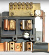
The early Wylex fuse box, not a consumer unit as type testing had not been started back then, often had reinforced contacts next to the 60 amp main switch, Wylex heavy duty.jpg so only one fuse could exceed 32 amp and it had to be next to main isolator Wylex 60 amp.jpg which was only rated at 60 amp, the DNO fuse back then would have been 60 amp, the consumer unit is allowed to go to 125 amp, only ever seen up to 100 amp, I have not seen a fuse box or CU bus bar which could not take 100 amp, but early days common not to use a bus bar but to daisy chain the fuse holders/MCB's.
 
Sponsored Links
Yea, it was the convention in the old days of rewireable fuse consumer units (Wylex, etc). This was because the busbar was quite small.
As a result, the early installs recommendation was for largest load nearest the main switch, then the next largest. And so the die was set.
Generations of electricians apprentices were told by their formen that was the way to do it.
All true.
But things move on and consumer unit construction and layout is now such that it doesn’t matter which order.
Probably (certainly that's what everyone seems to think). However (and although I've never heard of anyone applying this!), it appears that there may now be another consideration - namely that 'heavily loaded' MCBs/RCBOs are best not installed adjacent to one another. This might be because {in contrast with the fuses in Wylex Standard ones} modern CUs have MCBs/RCBOs in close physical/thermal contact). For example, sticking with Wylex, they now say ...

1653837201047.png


I'm not totally sure what they mean by a "66% diversity factor", but they are presumably talking about some sort of 'de-rating'. However, I've never heard of anyone considering this (maybe because domestic MCBs are rarely 'heavily loaded' for an hour or more?) - but it is perhaps worth being aware that this is at least a theoretical consideration which could (maybe should?) be taken into account when deciding upon the order of placement of MCBs/RCDs in a CU? It might be of much more potential relevance in non-0domestic installations?

Kind Regards, John
 
It's specified by most manufacturers of MCBs and other devices, and usually referred to as RDF or rated diversity factor.

In the case of 66%, that would mean a 32A device being only rated to 21A if it was to be fully loaded.
The factor depends on the number of fully loaded adjacent devices, with only 1 device RDF is also 1, but will decrease to less than 1 (or a percentage) as the number of fully loaded adjacent devices increases.

This is a Lewden example, other manufacturers are similar.

rdf_lewden.png


It's not usually a problem in domestic installations as most circuits are never fully loaded and even those that are (cooker, shower) are only loaded for a short time.
Two obvious exceptions are old style storage heaters and EV charging. Some manufacturers of EV supply equipment request a 40A device even though the equipment is only 32A.

The alternative is to install devices spaced apart, to improve heat dissipation.
This is an example I found a few weeks ago, 5 year old installation by others. Notable as all of the devices are spaced apart, and they are not in rating order either. Cooker circuit is 6mm² but only has an oven connected to it.

IMG_20220325_163933_HDR.jpg
 
It's specified by most manufacturers of MCBs and other devices, and usually referred to as RDF or rated diversity factor. .... In the case of 66%, that would mean a 32A device being only rated to 21A if it was to be fully loaded.
As I implied, that's what I presumed, but it seems to be somewhat contorted, potentially confusing and, in some senses, 'circular' language.

For a start, I'm not sure in what sense it is using the word "diversity". However, I find it somewhat confusing talking about a 32A device being 'fully loaded' at 21A, particularly given that it's operating characteristics (e.g. I1 and I2) will still; be defined by its In (i.e. 32A) - and that anyone coming across it in the future could perhaps be forgiven for regarding it simply as a "32A device".

What I'm finding particularly confusing (hence my reference to 'circular language') is that 'fully loading" a 32A advice would seem to mean that the load was 32A, yet application of the RDF would not allow it to be loaded beyond 21A - so it's really talking about a circuit that one would like to 'fully load' to the OPD's In), but cannot because of the need to apply an RDF.

The 'load' is likely to be something over which the designer/.installer has no direct control - i.e. if it's 32A, then it's 32A. It would therefore make more sense not to say that the 'rating' of the device had to be decreased by about a third but, rather, that, if the (continuous) design current was close to, say, 32A, then one had to use an MCB with an In of about 1.5 times that design current (i.e. ≥48A for a 'continuous 32A' circuit) - with the consequences that might invoke in relation to cable size. The only obvious alternative would be to split it into two circuits, with their own OPDs.

The factor depends on the number of fully loaded adjacent devices, with only 1 device RDF is also 1, but will decrease to less than 1 (or a percentage) as the number of fully loaded adjacent devices increases. This is a Lewden example, other manufacturers are similar.
Fair enough. Other than including the abbreviation "RDF", that wording is almost identical to Wylex's which I posted.

However, the situation seems less than clear from these texts (at least, to me). Are they saying (as you seem to be saying) that the RDF only has to be applied if two or more 'fully loaded' devices are 'adjacent' to one another? You (but not Wylex, and perhaps not Lewden) also say that when there are more than two adjacent 'fully loaded' ones, the RDF decreases, which sounds fair enough. However, to situation (how many adjacent 'fully-loaded' devices) does the Lewden table relate? Is that perhaps what they mean by "Consumer Unit Ways" (which I took to mean what it says, regardless of how many of the 'ways' contained 'fully loaded' devices)?

Kind Regards, John
 

DIYnot Local

Staff member

If you need to find a tradesperson to get your job done, please try our local search below, or if you are doing it yourself you can find suppliers local to you.

Select the supplier or trade you require, enter your location to begin your search.


Are you a trade or supplier? You can create your listing free at DIYnot Local

 
Back
Top