Poor wiring diagrams or poor understanding?

CBW

Joined
26 Sep 2019
Messages
19,439
Reaction score
7,253
Location
North
Country
United Kingdom
I thought I’d asked this before, but I can’t seem to locate the thread.

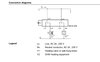
Why is it that certain manufacturer’s state a switched live as a neutral conductor, instead of stating switched output/live, or, is this my poor interpretation? (Examples below)

Is it that with all intents and purposes, that it eventually connects to neutral? :oops:
 

Attachments

  • 55D20475-5DAB-47D5-8278-2CE6729B9A4C.jpeg
    55D20475-5DAB-47D5-8278-2CE6729B9A4C.jpeg
    98.8 KB · Views: 150
  • 7B0EEFD0-24A1-42BD-A763-FFA17409A35B.jpeg
    7B0EEFD0-24A1-42BD-A763-FFA17409A35B.jpeg
    241.9 KB · Views: 145
  • D71A28A1-E845-4251-A023-686D9F4BA706.jpeg
    D71A28A1-E845-4251-A023-686D9F4BA706.jpeg
    79 KB · Views: 281
Sponsored Links
They don't actually state that the SL is Neutral because the rectangle (or other symbols) represents the appliance (load).

This, I am sure, is not clear to DIYers.
 
  • Thanks
Reactions: CBW
It would help to add a label for the connection that is the Switched Live.

When the switch is OFF then the Switched Live conductor does provide a path to Neutral via the load but it is NOT Neutral. Some equipment takes advantage of this by using the Switched Live conductor to provide a Pseudo Neutral to supply power to the electronics in the switch / thermostat / whatever,
 
  • Thanks
Reactions: CBW
1) Neutral and Line are both Lives so really should not use the word live unless referring to both.
2) Where we have a SELV there is no neutral, we have line 1 and line 2.
So only this
d71a28a1-e845-4251-a023-686d9f4ba706-jpeg.264074
set of diagrams of the three shown is fixed to a 230 volt supply as the anti-hysteresis heater and setback heater need 230 volt to work.

I have looked for yellow 110 volt cable at a reasonable price with the correct colours for a split phase supply with no neutral, and failed to find any, I am sure it exists some where, same with 110 volt plugs, they have the same L and N markings as the 230 volt version in spite of there being no neutral. I would guess some thing to do with the manufacturing process?

So which will most people understand upload_2022-3-14_10-56-27.png or upload_2022-3-14_10-59-53.png for feed and return? I would say for a universal label when you don't know if using a mains 230 low voltage supply or a power supply with a 24 volt separated extra low voltage supply then L and N are better than F and R or L1 and L2.
 
  • Thanks
Reactions: CBW
Sponsored Links
Each load has two connections one is always a permanent live or a switched live, the other being Neutral as shown
 
Each load has two connections one is always a permanent live or a switched live, the other being Neutral as shown
So it is basically connected to the neutral somewhere along the way?
 
So it is basically connected to the neutral somewhere along the way?
I am proberly not the best at explaining things.
Think of a basic lightbulb it has a Live and a Neutral to function , only divided and connected by the actual filament.
Your stat drawings can be used for various loads, fans, heaters, lights, hence they use a Rectangle symbol for the load, maybe replace that symbol with a light bulb and may help you understand a bit better.
 
  • Thanks
Reactions: CBW
Same with 110 volt plugs, they have the same L and N markings as the 230 volt version in spite of there being no neutral. I would guess some thing to do with the manufacturing process?
Single phase IEC 60309 ("CEEFORM") connectors don't distinguish different methods of earthing the supply. A supply with a nominal voltage in the range of 110V to 130V would use a yellow plug regardless of whether it was a P+N supply, a center tapped earth supply, or derived from a phase to phase connection on a three phase supply. Similarly a supply with a nominal voltage in the range of 200V-250V will use a blue plug regardless of it's earthing arrangement.

In the UK you are likely to find yellow plugs carrying split phase (of maybe two phases from three phase) and blue plugs carrying P+N supplies. In the US if IEC 60309 connectors are in use (they aren't as ubiquitous there as they are here) you are likely to find the opposite.

IIRC when I read the standard some time ago, there is supposed to be a L terminal, an earth terminal and an unlabeled terminal (which can be either a Neutral or a Second live depending on the supply type). The first photo I found on google showing the terminal labeling seems to follow this but I don't know how consistent manufacturers are on this.
index.php
 
So it is basically connected to the neutral somewhere along the way?
Why, I have worked on loads of equipment where there is no neutral.
Single phase IEC 60309 ("CEEFORM") connectors don't distinguish different methods of earthing the supply.
Yes I do agree, what one wants is some way to work out which wire is line 1, Line 2, Line 3, Neutral, earth or any other function and the only one which really matters is earth. We need to explain where wires go, so having U,V,W,X,Y,Z or 1,2,3,4,5,6 does not really matter, we can say connect the blue to 3 and 6, or yellow to 2 and 5 as easy as saying W and Z it just needs a label. OK we expect a motor terminal block to be U,V,W,X,Y,Z but nothing says that must be the label used.

upload_2022-3-14_14-54-44.png The wiring diagram without reading the key would make me think Y1 is the circulating pump and Y2 the boiler, as used with a typical C Plan central heating, clearly the same relay can be used for many other things, the instructions does show examples upload_2022-3-14_15-2-47.png on how the unit is used, so no real problem.
 
So, what makes the return path?

for part of the sine waveform when phase 3 is 230 Volts negative the positive currents going into the load on phase 1 and phase 2 will return to the substation as negative ( reverse direction ) current on phase 3

as the phase angle rotates then the current flows will alter accordingly

At all times the algebraic sum of the currents in the three phases will be zero. ( provided there is no Earth leakage in the load )
 
Last edited:
  • Thanks
Reactions: CBW
So, what makes the return path?
Clearly electric works as a circuit, so in the case of say a car, the electric in the form of electrons goes from the negative to the chassis and then powers some thing and returns on the positive wire.

We all know electric flows from positive to negative.

With AC not so defined, does it flow from neutral to line, or line to neutral, or of course line to line? So with a standard three phase motor the current flows between line 1, line 2 and line 3, and there is no current flow to neutral.

The same can apply with any split phase system, there is no need for anything to flow in the neutral.

Neutral simply means it is linked to earth, so we have either a delta secondary or a star secondary on the supply transformer
images
with delta we can centre tap one winding to give a neutral, in the main this is a USA system, but we can also have an IT system where there is no link to earth so no neutral.

OK not allowed in UK for most installations, but every bathroom shaver socket is an IT supply and there is no neutral.

I worked on a Robin tunnel boring machine with an IT 220 volt supply and I know the problems, I hope never to work on an IT supply again, but they do exist.
 
  • Thanks
Reactions: CBW

DIYnot Local

Staff member

If you need to find a tradesperson to get your job done, please try our local search below, or if you are doing it yourself you can find suppliers local to you.

Select the supplier or trade you require, enter your location to begin your search.


Are you a trade or supplier? You can create your listing free at DIYnot Local

 
Sponsored Links
Back
Top