Problem with RF room stat (salus rt300rf)

Joined
7 Dec 2008
Messages
15
Reaction score
0
Location
Kent
Country
United Kingdom
Hi.

Is there anyone on here willing to help me with a small problem?
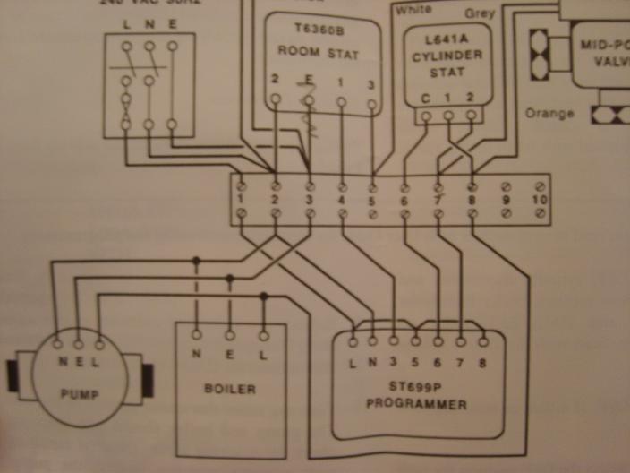
What it is, I have recently moved to a new house with CH but there isn't a room stat to control the heat, only a programmer (ST699P). The heating system is a Baxi (back boiler) with the following wiring layout (minus the room stat)


But instead of the Honeywell roomstat in the diagram, I want to install a SALUS RT300RF wireless stat (not programable version)..

The instructions to wire the SALUS are here: http://www.sensotec.co.uk/resource/pdfs/heating/RT300RF.pdf

I have it wired how I think it should be but the heating still comes on if the temp drops below the set value even if I turn the heating to the OFF position on the programmer (ST699P as in 1st pic)

I hope I've given enough info and would very much appreciate any pointers in the write direction. I want to do this myself as any sparky's that I've called want over £100 to do it, it's just 4 wires in a very easily accesable wiring center!!! way too much if you ask me!

Thanks in advance to anyone who can help.

Justin
 
Sponsored Links
Ignoring the fact that, unless I am going blind, you do not appear to have a permanent live to your receiver, I would be interested to know what voltages you are getting at terminals 4 & 5 with all states from the programmer.
 
Ignoring the fact that, unless I am going blind, you do not appear to have a permanent live to your receiver, I would be interested to know what voltages you are getting at terminals 4 & 5 with all states from the programmer.

I have tapped the (L) & (N) to terminals 1 & 2 on the wiring block.
 
Let me add some more info. As above, I've given the receiver power from terminals 1 & 2.
Terminal 3 & 4 were linked together, I'm assuming this was to override the fact that there was no room stat? I have taken out the loop and put the ON & OFF wiress from receiver to these 2 terminals..

As I've said the hot water and heating are working as they should but if I switch the heating to the OFF position from the CONSTANT position, the boiler still fires if the temperature drops below the setting on the room stat... something's not right eh!?!

thanks again.
 
Sponsored Links
Can you measure the voltages at terminals 4 & 5? you will need a multimeter.
 
Can you measure the voltages at terminals 4 & 5? you will need a multimeter.

Thanks for your replies, this is readings I have taken:

Using terminal 2 for the common.

PROGRAMMER SET TO OFF & STAT NOT CALLING: (T3)=240V - (T4) = 0V

PROGRAMMER SET TO CON & STAT NOT CALLING: (T3)=240V - (T4) =0V

PROGRAMMER SET TO OFF & STAT IS CALLING: (T3)= 156V - (T4) = 240V

PROGRAMMER SET TO CON & STAT IS CALLING: (T3)= 240V - (T4) = 240V

hope this helps?

and thanks again, it's much appreciated.
 
If it helps you understand this any better, I've used the wiring diag on page 4 (top one) of the SALUS manual as linked in my original post.


thanks
 
Can you measure the voltages at terminals 4 & 5? you will need a multimeter.

Thanks for your replies, this is readings I have taken:

Using terminal 2 for the common.

PROGRAMMER SET TO OFF & STAT NOT CALLING: (T3)=240V - (T4) = 0V

PROGRAMMER SET TO CON & STAT NOT CALLING: (T3)=240V - (T4) =0V

PROGRAMMER SET TO OFF & STAT IS CALLING: (T3)= 156V - (T4) = 240V

PROGRAMMER SET TO CON & STAT IS CALLING: (T3)= 240V - (T4) = 240V

hope this helps?

and thanks again, it's much appreciated.

I assume for 3 & 4 you mean 4 & 5 - otherwise you have 240V connected to earth.

Can you seperate the white from terminal 5 and determine where the voltage is coming from? i.e. the MV or the receiver. This is for your test #3 156v/240v

Sorry, yes I meant terminals 4 & 5. So You want me to remove the WHITE wire to see if the reading is still 156V right? I'll do that now.
 
Tchhh :LOL: T4 is FROM the programmer, T5 is TO the MV.

I now have no idea what you measured. Oh, and if you're going to do them again the volts at T6 would be helpful.
 
Tchhh :LOL: T4 is FROM the programmer, T5 is TO the MV.

I now have no idea what you measured. Oh, and if you're going to do them again the volts at T6 would be helpful.

T4 (on junction block) is from terminal 3 on programmer
T5 (on junction block) is white wire going to the MV

OK, I'll re-write what I should have in the 1st place:

Using terminal 2 for the common.

PROGRAMMER SET TO OFF & STAT NOT CALLING: (T4)=240V - (T4) = 0V

PROGRAMMER SET TO CON & STAT NOT CALLING: (T4)=240V - (T5) =0V

PROGRAMMER SET TO OFF & STAT IS CALLING: (T4)= 156V - (T5) = 240V

PROGRAMMER SET TO CON & STAT IS CALLING: (T4)= 240V - (T5) = 240V


With the same conditions that gave me the 156v reading, gave me a 76/240 reading when the white wire was removed.

You mention T6 but I am assuming that this is a reading from the immersion tank STAT and I'm having no grief with this one.

If you do want readings a T6, is this with or without that WHITE connected? of both?
 
Well, your're getting either high or reduced voltage from programmer terminal #3 to wiring centre terminal #4 when CH is off. It should be 0v at this point.

i don't understand why the Salus is passing 240V to #5 though, I thought it was a volt-free switch, so can't see how you can get 240V from 156 or 76 or whatever - Oh, I see you probably have the live to common link in and are just using the NO terminal for switching - can you clarify this?
 
Well, your're getting either high or reduced voltage from programmer terminal #3 to wiring centre terminal #4 when CH is off. It should be 0v at this point.

i don't understand why the Salus is passing 240V to #5 though, I thought it was a volt-free switch, so can't see how you can get 240V from 156 or 76 or whatever - Oh, I see you probably have the live to common link in and are just using the NO terminal from switching?

Looking at the SALUS manual, I wired it according to the 230V switching method and NOT the one below it, the volt free method! Should I wire it using the volt free method?
 
You don't need mains switching to get it to work.

Connect programmer #3 to terminal #4 to Salus common and remove the 230V link. Connect Salus NO to terminal #5 (MV white) and re-do all voltages.
 
OK, this is what I had done.

with the LINK (on salus) still in place:
Live from T1 to live on salus
N from T2 to N on salus
SL(ON) going to T5 and SL(OFF) going to T4
 

DIYnot Local

Staff member

If you need to find a tradesperson to get your job done, please try our local search below, or if you are doing it yourself you can find suppliers local to you.

Select the supplier or trade you require, enter your location to begin your search.


Are you a trade or supplier? You can create your listing free at DIYnot Local

 
Sponsored Links
Back
Top