
You are using an out of date browser. It may not display this or other websites correctly.
You should upgrade or use an alternative browser.
You should upgrade or use an alternative browser.
Project Help
- Thread starter wreck-it-steve
- Start date
- Joined
- 27 Apr 2008
- Messages
- 10,411
- Reaction score
- 1,241
- Country

Does the LED need to still light once the alarm has been silenced?
Yes until the aux contacts are back to normal
So does resetting the aux contacts on MCB1/MCB2 mean that the alarm also needs resetting?
If so what about the float switch? if this is latching at the alarm then it would need silencing at the alarm.
b*****r yes! (its been a few years since I last did this lol)
BRB.

Has been a whole 8 hours since I was working with a level alarm system!
- Joined
- 27 Apr 2008
- Messages
- 10,411
- Reaction score
- 1,241
- Country
Stevo66, who is to reset the alarm?
Has this to be latched and only reset by a set person or is it just once the fault has gone? I.E. its a non latching alarm.
I'm getting overcomplicated because I'm thinking from a fire alarm background and think about the requirements of keeping alarms from being reset by numpties at the panel.
Has this to be latched and only reset by a set person or is it just once the fault has gone? I.E. its a non latching alarm.
I'm getting overcomplicated because I'm thinking from a fire alarm background and think about the requirements of keeping alarms from being reset by numpties at the panel.
b*****r yes! (its been a few years since I last did this lol)
BRB.
Has been a whole 8 hours since I was working with a level alarm system!
This one seems the more simpler one but im still confused with your drawing... Can you explain a bit more please. How many relays in total are needed for your design and does it allow for the fload switch?
- Joined
- 27 Apr 2008
- Messages
- 10,411
- Reaction score
- 1,241
- Country
Stevo66, if nothing is to be latching on then use spark123's drawing but add resistors for leds.
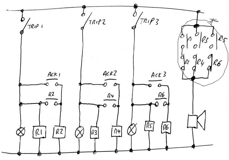
Mine was assuming that the remote unit is to remain latched irrespective of a change in the fault condition and that it can only be reset at the unit.
I was trying to do it with a single silence and reset buttons rather than 1 per circuit.
Mine was assuming that the remote unit is to remain latched irrespective of a change in the fault condition and that it can only be reset at the unit.
I was trying to do it with a single silence and reset buttons rather than 1 per circuit.
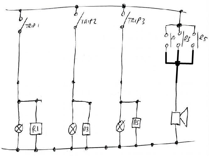
In my drawing there are 6 relays labelled R1 through to R6.
The float switch is just wired as any of the trips, i.e. use trip 3 if you like. When trip 3 closes the lamp will illuminate and R5 will energise. The contact for R5 will cause the sounder to alarm via the normally closed contact R6. When the acknowledge 3 button is pressed, R6 will energise and retain. This causes the sounder to silence as the normally closed contact will now be open. The lamp will remain on.
When trip 3 opens again (i.e. the water goes below high level) the lamp will go off, R5 and R6 de-energize and the system goes back into ready state.
When trip 3 is activated and silenced, either of the other two trips operating will cause the alarm to sound again i.e. ack3 does not inhibit the sounder function of either of the other two alarms, you will need to press ack for the relevant alarm.
If trip 3 activates, the lamp will illuminate and alarm will sound. If the water then goes down again the system will reset back to its ready state on its own.
In my drawing there are 6 relays labelled R1 through to R6.
The float switch is just wired as any of the trips, i.e. use trip 3 if you like. When trip 3 closes the lamp will illuminate and R5 will energise. The contact for R5 will cause the sounder to alarm via the normally closed contact R6. When the acknowledge 3 button is pressed, R6 will energise and retain. This causes the sounder to silence as the normally closed contact will now be open. The lamp will remain on.
When trip 3 opens again (i.e. the water goes below high level) the lamp will go off, R5 and R6 de-energize and the system goes back into ready state.
When trip 3 is activated and silenced, either of the other two trips operating will cause the alarm to sound again i.e. ack3 does not inhibit the sounder function of either of the other two alarms, you will need to press ack for the relevant alarm.
If trip 3 activates, the lamp will illuminate and alarm will sound. If the water then goes down again the system will reset back to its ready state on its own.
Does the relay count go down if there is no alarm silence button?
Yes, you can get away with 3 relays.
Rob gave a method for this in the second post, you could drop down to SPST relays and put the lamps across the coils instead if you wanted. Use the contacts in parallel for the buzzer.
Rob gave a method for this in the second post, you could drop down to SPST relays and put the lamps across the coils instead if you wanted. Use the contacts in parallel for the buzzer.
Yes, you can get away with 3 relays.
sorry to be a pain but could you show me the drawing without the silence button?
(I have left the relay numbers as 1, 3 and 5 as am using another PC so just used the DIYnot editor, in reality you'd number them 1, 2 and 3)
I also edited the original pic to put some missing links into the relay logic

In my drawing there are 6 relays labelled R1 through to R6.
The float switch is just wired as any of the trips, i.e. use trip 3 if you like. When trip 3 closes the lamp will illuminate and R5 will energise. The contact for R5 will cause the sounder to alarm via the normally closed contact R6. When the acknowledge 3 button is pressed, R6 will energise and retain. This causes the sounder to silence as the normally closed contact will now be open. The lamp will remain on.
When trip 3 opens again (i.e. the water goes below high level) the lamp will go off, R5 and R6 de-energize and the system goes back into ready state.
When trip 3 is activated and silenced, either of the other two trips operating will cause the alarm to sound again i.e. ack3 does not inhibit the sounder function of either of the other two alarms, you will need to press ack for the relevant alarm.
If trip 3 activates, the lamp will illuminate and alarm will sound. If the water then goes down again the system will reset back to its ready state on its own.
In this version you say there are 6 relays but what is the part what i have circled?
Wire everything back to its own pin on an arduino, and then you can come up with as many torturous designs for how it fits together as you like. Big transistor to drive the sounder, same for LED's if you're using superbrights or ones that want to be driven at 24v or whatever.
DIYnot Local
Staff member
If you need to find a tradesperson to get your job done, please try our local search below, or if you are doing it yourself you can find suppliers local to you.
Select the supplier or trade you require, enter your location to begin your search.
Please select a service and enter a location to continue...
Are you a trade or supplier? You can create your listing free at DIYnot Local
Similar threads
- Replies
- 4
- Views
- 4K