B
busterboy
Hi
Im new to forum and just want to ask a question.
(Refer to diagram 1 for this part)
I live in an old stone cottage that over the years has had kitchen extension on back and one bedroom added at front upstairs.
This will be a bit hard to explain but please bare with me.
Because of the age of the house a new kitchen has been added to the back and built on to the stonework and the same for the upstairs bedroom (Bedroom 3)
I have made a diagram to try to explain this better. But above bedroom 1 have floored the loft and this is where i want to add a double socket.
in the other half of the house is loft 2 but these lofts are separated by the new bedroom upstairs (bedroom 3). all wiring that goes from one side of the house goes through bedroom 3's floor boards.
Again I'm sorry for the confusion but just trying to explain the setup before i ask about my question.
(Refer to diagram 2 for this part)
Now in bedroom 1 there is only one double socket and it looks to be a spur as it only has one cable going to it. so i don't think i can use this to spur of for another socket in the loft 1 which is directly above it???
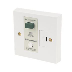
but in loft 2 there is a spur running out to the outbuilding with 3 sockets linked to it. where it leaves loft 2 there is an what looks to be a mini trip or switch with ON/off on it. (I can provide pictures if this helps.) when its one the outbuilding sockets work and when you flip it to off they don't so that's fine.
(diagram 3)
Now for my question if you are still with me lol! I am thinking about disconnection the wire that runs from loft 2 to the out building and adding a new wire to the on/off trip switch that will follow back through the floor boards of bedroom3 and into loft 1 so i can add a double socket to it. i have outlined this is a basic diagram to try to explain it better. i would be great full if someone can point me in the right direction on this and advise me if this would work. I don't need sockets in the outbuilding and have ducting already in place for the stone walls so the new cable will install easy. I also think the on/off switch could be a fcu as the outbuilding sockets seem to be spurred from the house but not sure about this hence any advice welcome. i can provide photo of this switch if necessary.
Thank you.
P.S
Not sure how to upload my digrams but i think there in an albums section if thats any use.
Im new to forum and just want to ask a question.
(Refer to diagram 1 for this part)
I live in an old stone cottage that over the years has had kitchen extension on back and one bedroom added at front upstairs.
This will be a bit hard to explain but please bare with me.
Because of the age of the house a new kitchen has been added to the back and built on to the stonework and the same for the upstairs bedroom (Bedroom 3)
I have made a diagram to try to explain this better. But above bedroom 1 have floored the loft and this is where i want to add a double socket.
in the other half of the house is loft 2 but these lofts are separated by the new bedroom upstairs (bedroom 3). all wiring that goes from one side of the house goes through bedroom 3's floor boards.
Again I'm sorry for the confusion but just trying to explain the setup before i ask about my question.
(Refer to diagram 2 for this part)
Now in bedroom 1 there is only one double socket and it looks to be a spur as it only has one cable going to it. so i don't think i can use this to spur of for another socket in the loft 1 which is directly above it???
but in loft 2 there is a spur running out to the outbuilding with 3 sockets linked to it. where it leaves loft 2 there is an what looks to be a mini trip or switch with ON/off on it. (I can provide pictures if this helps.) when its one the outbuilding sockets work and when you flip it to off they don't so that's fine.
(diagram 3)
Now for my question if you are still with me lol! I am thinking about disconnection the wire that runs from loft 2 to the out building and adding a new wire to the on/off trip switch that will follow back through the floor boards of bedroom3 and into loft 1 so i can add a double socket to it. i have outlined this is a basic diagram to try to explain it better. i would be great full if someone can point me in the right direction on this and advise me if this would work. I don't need sockets in the outbuilding and have ducting already in place for the stone walls so the new cable will install easy. I also think the on/off switch could be a fcu as the outbuilding sockets seem to be spurred from the house but not sure about this hence any advice welcome. i can provide photo of this switch if necessary.
Thank you.
P.S
Not sure how to upload my digrams but i think there in an albums section if thats any use.

")