Rather techy DHW question...

Sponsored Links
fine i will watch with interest and see if anyone can conclusively say it works, because they have done it or it doesn't work, because they've tried it and it didn't.

:rolleyes: :rolleyes: :rolleyes:
 
kevindgas said:
fine i will watch with interest and see if anyone can conclusively say it works, because they have done it or it doesn't work, because they've tried it and it didn't.

:rolleyes: :rolleyes: :rolleyes:

I have done these on heat banks - similar thing.
 
great so finally someone has tried it !

so how does it work when you've drawn hot water off through the taps and you turn off tap. the water in the circuit is precooled to say 45 degrees now it goes back to cylinder at 45 degrees mixes with the hotter water in the cylinder and comes back out and round circuit. surely that would have a cooling effect on the cylinder?
i have a return hot water circuit on mine but don't have the TMV and yes i lose a few degrees (about 5 per hour) when there is no input from boiler or solar.
 
Sponsored Links
I've lost track of what "it" is and whether "it " will work!
 
4zy22qr.jpg


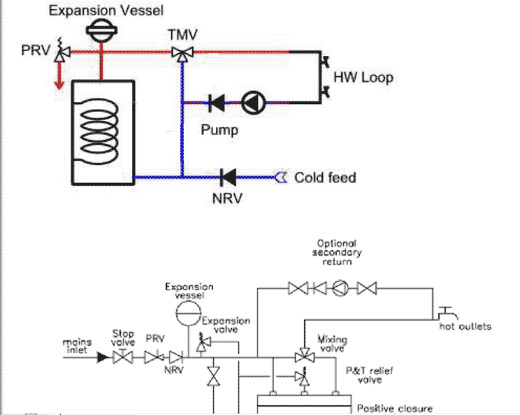
We're talking about this set-up (I think). There is a section of the pipework where flows might be in either direction depending on the position of the TMV and whether there is a draw off of hot water. I can't see why this should be a problem but others seem to think it will be. Interested to know what you think.
 
The ACV one looks OK.
Isn't yer valve the wrong way round...
2ndryreturns.gif
 
Yes, the TMV is drawn (by OP) with the wrong orientation but I've assumed everybody understands that. Do you think the juxtaposition of the secondary return connection and cold inlet to cylinder makes any difference? That's the only difference that I can see between the two diagrams.

By the way, how did you manage to lift the diagram from the ACV adobe file?
 
kevindgas said:
great so finally someone has tried it !

On heat banks and this reversal flow though one section of the pipe does not occur.

Heat Banks provide Secondary Circulation by the usual means, except the return tees into the mains in above the flow switch. The heat exchanger pump can be brought on by a pipe thermostat fitted to the secondary return loop that will result in the loop being reheated once it has dropped to stat setting. A clock should always be used on all secondary circulation loops. I have implemented a couple of infra red sensors that bring in the secondary circulation pump. E.g., walk in the bathroom and the pump starts. Walk out and it stops.

so how does it work when you've drawn hot water off through the taps and you turn off tap. the water in the circuit is precooled to say 45 degrees now it goes back to cylinder at 45 degrees mixes with the hotter water in the cylinder and comes back out and round circuit. surely that would have a cooling effect on the cylinder?

It will cool the cylinder, however the cooler water is being pumped into the bottom cooler section anyway. Secondary circulation pumps are just "circulators" and only need to move the water in the loop "very" slowly. It will not upset stratification in the cylinder. Also, having a pipe stat on the loop will stop the pump cooling the cylinder too much.

i have a return hot water circuit on mine but don't have the TMV and yes i lose a few degrees (about 5 per hour) when there is no input from boiler or solar.

TMVs will be the norm and they do complicate matters a little as this thread has shown. You need a clock and pipe stat to prevent overcooling of the cylinder and make sure the pump is just turning - the lowest speed and restrict flow down to suit.
 
chrishutt said:
Yes, the TMV is drawn (by OP) with the wrong orientation but I've assumed everybody understands that. Do you think the juxtaposition of the secondary return connection and cold inlet to cylinder makes any difference? That's the only difference that I can see between the two diagrams.

There will be no to little difference in practice if the loop return is in 15mm and is taken right up to the TMV - which it should be on any system. The cold water pressure will take the water from the loop back through the TMV warming up the water somewhat and preventing it passing through the cylinder.

On any of these mains pressure secondary return loops, when drawing of large volumes of hot water, the pressure in the loop (after the TMV) may be far less than the incoming mains pressure. This may mean the non-return valve after the pump will be locked shut by the incoming mains and the pump not strong enough to open it, pumping on nothing. Hopefully the loop would have been up to temp and the pipe stat had switched out the pump. The pipe stat should always be set below the TMV setpoint.
 
chrishutt said:
By the way, how did you manage to lift the diagram from the ACV adobe file?

The "snapshot" tool will put the sectioned piece on the clipboard, then paste into PaintShop or whatever. If no snapshot then zoom in and use the "print screen" key. Paste into PaintshopPro and cut out the bits you do not want.
 
The TMV can be used on the cylinder because it requires a hot and a cold feed.

However, the secondary pumped loop is not compatible with the TMV because the return should go to a tapping near the top of the cylinder where the water is assumed to be always hot.

If the pumped return goes to the cold bottom of the cylinder it will return heated water to the bottom and cool the water at the top if the cylinder is half cold and reheating.

The secondary pumped loop WOULD work if the pump operation was inhibited when the base of the cylinder is cold using a thermostat near the bottom of the cylinder.

Alternatively it would be OK if the pump was inhibited by a pipe stat on its output set close to the mixed water temperature, say 40° C if the TMV is at 50° C.

Tony
 
Agile said:
The TMV can be used on the cylinder because it requires a hot and a cold feed.

However, the secondary pumped loop is not compatible with the TMV because the return should go to a tapping near the top of the cylinder where the water is assumed to be always hot.

If the pumped return goes to the cold bottom of the cylinder it will return heated water to the bottom and cool the water at the top if the cylinder is half cold and reheating.

Pay attention at he back!!! That is why you insert a pipe stat to switch out the pump when the loop is up to temp.

Alternatively it would be OK if the pump was inhibited by a pipe stat on its output set close to the mixed water temperature, say 40° C if the TMV is at 50° C.

Good he got it!
 
ChrisR said:
The ACV one looks OK.
Isn't yer valve the wrong way round...
2ndryreturns.gif


The details in the two diagrams are the same, except the OP should have the expansion tank on the cold feed, as in the ACV detail.

The bit that is confusing is that the LH connection on the top of the ACV diagram is the cold feed. This is an internal dip tube taking the cold feed &/or HWS R to the bottom of ACV store cylinder. This isn't apparent on Dr. Drivel's cut and paste and there are no direction arrows to show this.
 
Onetap wrote

The details in the two diagrams are the same

No their not the same. If you have ever fitted an ACV unvented cylinder(unlikely) then you would see this.
 

DIYnot Local

Staff member

If you need to find a tradesperson to get your job done, please try our local search below, or if you are doing it yourself you can find suppliers local to you.

Select the supplier or trade you require, enter your location to begin your search.


Are you a trade or supplier? You can create your listing free at DIYnot Local

 
Sponsored Links
Back
Top