RCBO Tripping

I will put the drummond onto the effected circuit at the terminals of the two RCBOs and then in to each socket with the breakout plug.

With the loose neutral I was wondering if the kitchen is on position 2 (and unaffected) the down is on position 3 slightly further along the busbar from the neutral connection to the main switch, is effected both when it is loaded and when the Up circuit in position no 4 is loaded. as we go along the busbar we have a spare place for later use (garden shed feed) and then the lighting circuits (up and down) ie No shower or cooker here at all.
 
Sponsored Links
I will put the drummond onto the effected circuit at the terminals of the two RCBOs and then in to each socket with the breakout plug.
Good. I look forward to hearing the outcome. Of course, if you get different results on the load terminals of an RCBO and on sockets on the same circuit, then you will have a (even greater) problem on your hands :)

Kind Regards, John

Obviously I will be testing with the outgoing wires detached.
 
I will put the drummond onto the effected circuit at the terminals of the two RCBOs and then in to each socket with the breakout plug.
Good. I look forward to hearing the outcome. Of course, if you get different results on the load terminals of an RCBO and on sockets on the same circuit, then you will have a (even greater) problem on your hands :)
Obviously I will be testing with the outgoing wires detached.
If you get an RCBO (or any other RCBO/RCD in the installation) to trip by just connecting a lamp across its output terminals (with absolutely nothing else connected to the RCBO) then, in the absence of N-E faults (which you appear to have excluded), I really would be pretty amazed!

Kind Regards, John
 
Sponsored Links
Thought from non electrician....
Someone hasn't used the N or CPC of the socket circuit for a lighting link?
 
Thought from non electrician....
Many of the thoughts that Martin have so far received have been from us non-electricians :)
Someone hasn't used the N or CPC of the socket circuit for a lighting link?
Using the CPC for some other circuit would not do any harm (all CPCs are joined at the CU). Using the N could, indeed, result in RCD/RCBO tripping, but, as far as can see, not the pattern of behaviour that Martin has described.

Kind Regards, John
 
Many of the thoughts that Martin have so far received have been from us non-electricians :)
That may be from the theorists amongst us.

From a practical point of view, what Martin says cannot happen so what can anyone suggest?

If the IR tests are as stated it is not possible.

I am not disparaging Martin but he (you) must have missed something.

There must be a connection between the two circuits or -


as being discussed in the other tread there is always a voltage on the neutral and it must also be connected to true earth.

Now, wouldn't that be a turn up?
 
That may be from the theorists amongst us. From a practical point of view, what Martin says cannot happen so what can anyone suggest? If the IR tests are as stated it is not possible.
I agree - with a single, incredibly unlikely, exception - if the two circuits were in some way connected via a capacitor {not 'stray capacitance', which I just don't believe would do it}, hence the connection not detectable with a DC IR test. However, even with an overt connection, detectable by IR tests, one would not really expect the pattern of results which Martin described - which is why I suggested he tried swapping the RCBOs, to discover to what extent the observed behaviour was a consequence of different operating characteristics of the two devices.
I am not disparaging Martin but he (you) must have missed something.
There must be a connection between the two circuits or -
as being discussed in the other tread there is always a voltage on the neutral and it must also be connected to true earth.
That certainly sounds 'almost' right - the complication being that, whilst they might explain some tripping, I'm not sure that either of those explanations, alone, would be expected to given the pattern of behaviours described.

Kind Regards, John.
 
As I said I have tested between like for like (N-N, L-L etc) between the two circuits, but I have not tested if there might be a lowish resistance between L of down and N of up circuit. But it kind of defies Kirchoffs Law the way I am describing, so I must have cocked up the testing somewhere or something has been plugged in that is causing the fault between the two circuits like a tv amp taking a N fault upstairs to a the circuit downstairs via a back box or tv.
I have drawn out the circuits for each of the faults and something was missed. I was under time pressure to get off site and had I known that would happen I would not have done the job on that day at all.
I can't see it being the RCBOS
I can't see that the circuits are DC connected (Well at least not to the same wire in the other circuit)
So that leaves to my mind a loose connection or inductive/capacitive link
But I will unwire the whole thing and repeat all the dead tests plus further IR testing between every conductor
 
... so I must have cocked up the testing somewhere or something has been plugged in that is causing the fault between the two circuits like a tv amp taking a N fault upstairs to a the circuit downstairs via a back box or tv.
I'm not sure about the 'or'. Even if there is some device which is in some way cross-connecting the two circuits, you presumably would/should have picked that up with your tests.
I can't see it being the RCBOS
Nor can I - but, whatever the primary cause, an appreciable difference in operational characteristics of the two RCBOs might possibly explain the puzzling asymmetry of the behaviour you reported - which is why I said it would be interesting to see if that asymmetry 'reversed' if one swapped (the connections to) the two RCBOs in question. I'm also gradually coming to the conclusion that it would be hard to postulate any way in which a single issue could result in what you're seeing.
So that leaves to my mind a loose connection or inductive/capacitive link
As I said before, I really do very seriously doubt that it could be due to an inductive/capactive link bewteen the wiring of the two circuits. As for a loose connection, as I wrote earlier today, I can think of one way that it could introduce a type of link between circuits. However, I've been thinking about this and, since that link would be on the supply side of the RCBOs, I can't really see how it could explain any of what you're seeing.

As EFLI wrote, if one ignores the 'incredibly unlikely', what you are reporting does essentially seem 'impossible' - and when that happens to any of us, it usually means that we are 'missing something' or doing something silly (and I, for one, am far from immune from that!).

Kind Regards, John
 
Have you made absoluotely certain you've not got one or both of your lives / neutrals mixed up at the CU?

That was my first port of call, but each neutral rings out and so do the lives - I even crossed them over (one pair of neutrals to the same RCBO as the other pair of Lives) to check check that the sockets would be dead -and they WERE

I also (and sorry to everyone for forgetting this clue) put everything onto one rcbo so that both circuits shared the same RCBO - and guess what - the RCBO tripped straight away.
 
I also (and sorry to everyone for forgetting this clue) put everything onto one rcbo so that both circuits shared the same RCBO - and guess what - the RCBO tripped straight away.

That adds weight to the possibility of a neutral to ground fault being the cause.

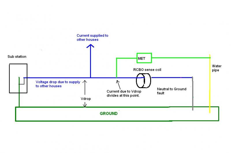
Try the same but with the RCBO's live output disconnected. If it still trips then it can only be current on the neutral through the RCBO sense coil and that has to involve a neutral to ground current. That current could be flowing from a neutral to a CPC fault and then via a CPC to ground connection such as a bonded metallic service pipe.
 

Although the path to ground via the water pipe or other bonded service is very low impedance any current due to Vdrop will still be shared with the path through the sense coil and this can easily result in more than 30 milliAmps passing through the sense coil. ( I have measured over 100 milliAmps flowing from a CPC (derived from incoming neutral) down to an earth rod )

One thing that comes to mind, is the MET actually connected to the incoming neutral ?

If not then a neutral ground or neutral CPC fault would put all the current from Vdrop through the sense coil.
 
I'm a little confused, since this almost seems like a response to the exchanges Bernard and I are having in the 'other thread'. Anyway, in terms of this thread, a couple of points.

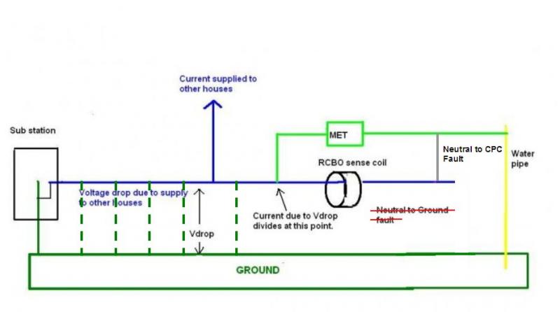
Firstly, you have drawn a TN-C-S system, but without the PME. If one adds the multiple earth connections (see below) the PD between the incoming neutral (hence MET/CPCs) and true earth will be consdierably less than the voltage drop in the supply neutral cable (your "Vdrop").

Secondly, and most importantly, your diagram relies on a N-to-True Earth resulting in operation of the RCBO. However, there is no way that plugging in a test appliance could create that (if anything, it would create an N-CPC fault, as illustrated below). If it were a 'permanent' N-True Earth fault (i.e. in fixed wiring), the RCBO would obviously be permanently tripped. The only way I can see your hypothesis being relevent would be if there were a permanent N-True Earth fault on the circuit resulting in a current <30mA flowing through the RCD AND Martin was using a test appliance which introduced a further N-CPC fault, tipping the current imbalance in the RCBO beyond the 30mA threshold. That seems very unlikely but is, in any event, the reason I suggested he tried with a different (simple, smaller and resistive) test load.

Kind Regards, John
 
Yes this is a TN-S installation. I can't see the neutral fault being a candidate as I have measured the resistance and it is in the order or hundreds of MOhms for the earth neutral. I can't (even me) have cocked that measurement up.
I think that there is a resistance between the live of of one circuit and the neutral of another. As this is the only thing that could have escaped my measurements to date.
 

DIYnot Local

Staff member

If you need to find a tradesperson to get your job done, please try our local search below, or if you are doing it yourself you can find suppliers local to you.

Select the supplier or trade you require, enter your location to begin your search.


Are you a trade or supplier? You can create your listing free at DIYnot Local

 
Sponsored Links
Back
Top