So the DOWN RCBO in case 1 or 2 (below) saw an imbalance and tripped. The UP RCBO is capable of doing its job once the DOWN live has gone, suggesting no L to CPC or GND leak or no N to CPC or GND leak on the up circuit.
If the neutral for the DOWN circuit was somehow going to GROUND (not the CPC but GROUND) then I can see a way that all 3 conditions (see below) you list could coexist.........
1)
If any socket on the Up circuit is used - the RCBO for down trips, but the up circuit stays on and continues to work
The send & return currents for the UP circuit are fine and there's no connection to another circuit, however when the neutral current returns through the CU busbar, part of it returns to the incoming neutral and part goes through the down RCBO neutral to GND, tripping the down RCBO. JohnW2's suggestion of using a small resistive load to see what maybe happening here I think is a good one. As neutral current increases due to the load on the UP sockets the amount of current going to GND would also increase to where it would trip the DOWN RCBO.
The UP RCBO never saw an imbalance because there wasn't one.
2)
If any socket on the down circuit is used the down RCBO trips.
Essentially the same although the current path is a little different and some of it goes to GND directly now, again tripping the down RCBO.
3)
put everything onto one rcbo so that both circuits shared the same RCBO - and guess what - the RCBO tripped straight away.
Is possibly the most interesting combination as now you don't even need to plug in a load anywhere to get it to trip. Previously the system was managing to 'deal' with a 'fault' that appeared with the plugging in of a load by tripping out. Now it can't even do that and never stays in. It might be this configuration that's easiest to troubleshoot. In this state I would check its resistances L to E and N to E and then also L to ground if possible, and N to Ground if possible, with the two circuits connected together like you've said but not into the RCBO.
I was going to say that (and this links to the other RCBO tripping discussion) by having the neutral and GND (two low impedance sources) connected together, small voltage differences cause large currents. But that wouldn't explain why the down RCBO ever stays in. Maybe the connection of the 2 circuits joined together is enough wiring to pick up enough noise to do the job of tripping it? Noise pickup will be directly proportional to loop area.
Once the down RCBO has tripped ( the only RCBO that monitors a path to the fault) the fault is still present ( as the RCBO only disconnected the line) and none of the other RCBOs can respond to it as everything else balances as far as they're concerned. On an old board with no RCD/RCBOs you'd never of seen the fault.
http://www.scribd.com/doc/62863090/35/Capacitance-to-Earth#page=36
The RCD Handbook, A BEAMA guide to the Selection and Application of Residual current devices.
9.2 Capacitance to Earth
The capacitance of 1.0,1.5,and 2.5mm2flat thermoplastic insulated twin and earth cable isapproximately 150pF per metre.It would not be unusual for a domestic installation to have100m of 2.5mm2cable and 250m of 1.0 or 1.5mm2cable,which would result in acapacitance to earth of up to 52.5nF.This would allow a standing protective conductorcurrent of 11µA/m or a cable leakage current of nearly 4mA for the whole installation (at230V,50Hz).
Bunched cables would have multiple stray capacitors with a live in each cable forming a capacitor with the earth in ajacent cable(s) as well as forming a capacitor with its own earth. Thus a higher overall capacity than for the same length of cable un-bunched.
One thought about their figure of 150pF/M. I've just stuck a capacitance meter across an old, regular 6.8M long piece of 2.5 T&E. L-E measured 880pF and N-E 875pF, so it's coming up at about 130pF/M. Fine, not a bad match for their 150pF/M. But that's for 2 wires in intimate uniform contact along their entire length. ie for the same piece of cable or a radial leg.
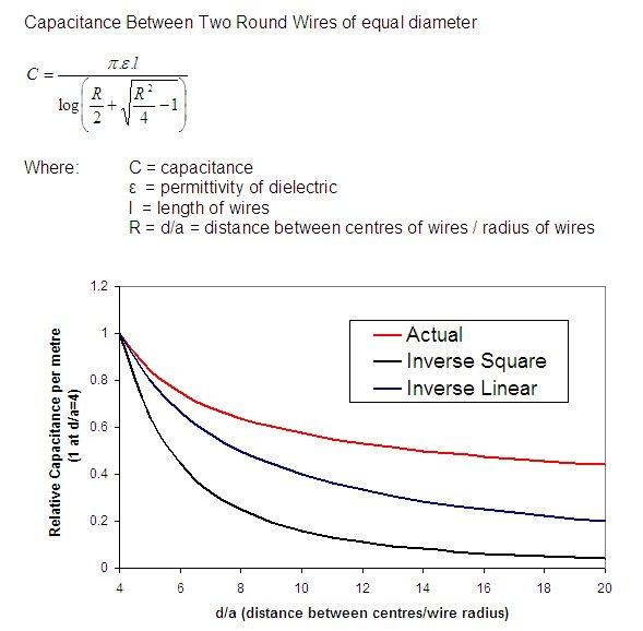
The capacitance will tail off with cable separation, I was going to guess that the rate of tail off would be inverse square law but it turns out that parallel wires are an inverse natural log function, so perhaps inverse square like, if my dodgy maths holds up. But either way the capacitance will fall away fairly quickly with even a small distance from cable to cable. So for that reason even if these cables were sandwiched together in conduit, I'd guess their capacitive coupling wouldn't approach 130pF/M. Add to that that they'll probably not be close coupled for that far in a house before they go their seperate ways, so I doubt the effect you see would be inter cable capacitance. Unless the system was so close to the edge that the RCDs were on a hair trigger for other reasons.


")