RCD Top or Bottom Supply.

Joined
12 Jan 2006
Messages
185
Reaction score
3
Country
United Kingdom
Evening all,

My second thread in one day after not posting one for many moons!

My neighbour has purchased a BG RCD CUR4030 to mount in a stand-alone unit (to replace an existing stand-alone unit that got damaged, also the test-button would not function).

Does it matter which way round the input and output go.

It would be easier for the supply to enter via the bottom and load exit via the top.

I have read myself that a lot of rcd manufacturers say it does not matter but I have heard some people say some RCDs don't like it.

Many Thanks
 
Sponsored Links
It shouldn't matter. The convention is the incomer goes in the top because the busbar goes in the bottom.

What does the diagram on the front say? Anything helpful?
 
With most three phase boards the husband are above the RCD so as said it should not matter in most cases.
If one thinks about how they work, it's very difficult to see how it can ever make a difference, when the device is 'closed'.

The only possibility I can think of is that if (as is usually/always the case) they contain electronics (usually powered from the supply side), it might conceivable not be possible to reset the device, since the electronics would not be powered until it had been successfully reset. However, in that situation, it would be immediately obvious that there was a problem. I can't think of any way there could be a problem once it was reset (if it would).

Kind Regards, John
 
Sponsored Links
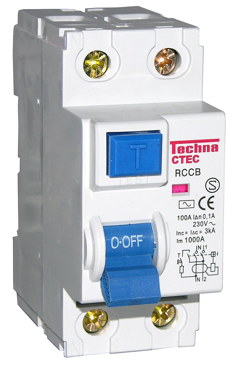
800px-Residual_current_device_2pole.jpg
This picture from Wikipedia shows if the supply enters from the top, then once tripped the internal circuitry is also isolated, so it would be better with this model if supplied from top,
full
with complex types, the second one auto resets, then yes it will matter which way around they are wired, but for most it will not matter, they will still work, and of course when fitting a RCD you will test anyway so if the model you have does need the feed at a set end, you will know as it will fail the test.
 
This picture from Wikipedia shows if the supply enters from the top, then once tripped the internal circuitry is also isolated, so it would be better with this model if supplied from top, ...
Maybe, but as I said, there is a theoretical possibility (depending upon how it's designed) that once "the internal circuitry is also isolated", it might not be possible to reset it, because the electronics would not have any power until it was successfully reset.

Kind Regards, John
 
Have you got that the right way round?

Eric's picture and all that I can find show the "normal" wiring arrangement isolates the internal circuitry when open.
 
Have you got that the right way round?
My argument is, I think, the right way around, but .....
Eric's picture and all that I can find show the "normal" wiring arrangement isolates the internal circuitry when open.
If that's the case, then what I was suggesting cannot be how it ever is. I was just thinking that it might be the case with some of them that it was impossible to get them to 'latch on' (i.e. 'reset') unless/until the electronics was powered - which, if I remember correctly, is the case with at least some active RCDs.

Edit: Hang on - does Eric's picture necessarily indicate that the electronics are isolated from power when the main RCD contacts are open??

Kind Regards, John
 
With an active RCD then as you say maybe electronics need power, however in a consumer unit we normally use passive RCD's which will not trip with power failure so it really would not matter.
 
With an active RCD then as you say maybe electronics need power, however in a consumer unit we normally use passive RCD's which will not trip with power failure so it really would not matter.
I obviously know that. My point was simply that active RCDs demonstrate that it is possible to make an RCD which cannot be manually reset without the electronics being powered - so I wondered if their might possibly be some passive ones whose electronics exhibited corresponding behaviour.

If that were the case, and if the electronics were powered from the 'supply side' of the RCD, then one would not be aware of any issue when the supply was, indeed, connected to the 'supply side', but there could be a problem if the supply were connected to the 'load side'.

I'm not saying that such is ever the case (it very probably isn't) but, in the context of this discussion, was just pointing out that there is a theoretical possibility that some (passive) RCDs might need to be connected a particular way around.

Kind Regards, John
 
I do not really understand what you are getting at. What would the advantage be of powering the electonics when the device is switched off?

Surely, even with all the electronics on the load side, they would be energised when you switch it on - much like my 'active' kettle switch.
 
I do not really understand what you are getting at. What would the advantage be of powering the electonics when the device is switched off?
It might not be merely an advantage, but possibly actually essential, if the design were such that the device could only be 'latched' into the closed position with the electronics powered.

However, it quite possibly is never like that (with a passive RCD) - I have certainly used standard RCDs 'both ways around' without any problems. This started because I merely suggested a possible mechanism to support the fact that eric had included "in most cases" in his early statement ...
... so as said it should not matter in most cases.
In other words, it is not impossible that there are exceptions, so "most" is probably safer than "all".

Kind Regards, John
 

DIYnot Local

Staff member

If you need to find a tradesperson to get your job done, please try our local search below, or if you are doing it yourself you can find suppliers local to you.

Select the supplier or trade you require, enter your location to begin your search.


Are you a trade or supplier? You can create your listing free at DIYnot Local

 
Sponsored Links
Back
Top