Re wire light switch?? lost picture!

Joined
29 May 2010
Messages
67
Reaction score
0
Location
Lancashire
Country
United Kingdom
Hi,

I took a picture of how a light switch was wired before i removed from conduit and chased wires into wall. Now I have lost my phone with the pictures!

it is a 6 way light switch which i belive only controls 3/4 lights.

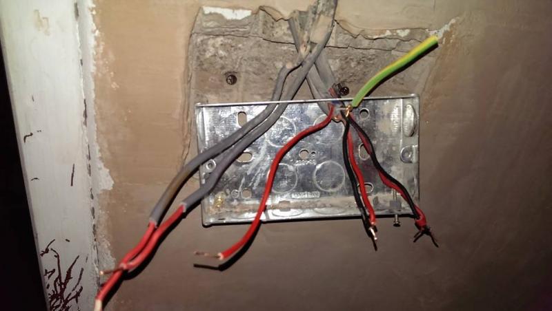
I have the following wires - Single red core x 2, single live/earth x 1, twin earth x 2.

1 of the black wires from the twin/earth has red sheth on so im guessing that is a switch live and so are the single red cores.


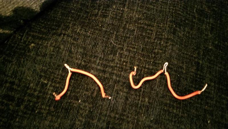
2 x red wire bridge M shaped so bridges into 3 so permanent live can be bridged into all COM slots?

any idea of how to rewire this back up im baffled and cannot belive i have lost the picture.

i will upload pics soon but it as explained above..
 
Sponsored Links
Why did you remove conduit and chase cables in?

Do you have unsheathed single cables chased into wall?

Have you added new cables and buried them also, if so are these RCD protected?

Did this conduit form any part of the earthing of the circuit?
 
Sponsored Links
everything is rcd protected and all the cables are sheathed, i have converted the back of the garage into a room so wanted the cables hidden. unfortunatley i do not have a multimeter
 
everything is rcd protected and all the cables are sheathed, i have converted the back of the garage into a room so wanted the cables hidden. unfortunatley i do not have a multimeter

Are sure they are sheathed, the sheath is the grey, sometimes white or black PVC coating, not the red or black insulation.

It would be very difficult to guess the previous installers methods or what was in their head at the time.
Really need some form of testing.
 
it is a 6 way light switch which i belive only controls 3/4 lights.

What does that mean?

It would certainly make sense where you describe a permanent live wire will be looped to feed other switches.

However, it is is quite possible some of the switches MAY NOT be fed in this manner. Often switches can be wired in very strange ways, depending on the history of the building, where additions have been made and so on.

Also, could some of the switches have been 2 way - ie is there another switch somewhere providing a 2 way function?

Also, is there more than one circuit supplying this bank of switches? If so, you certainly don't want to mix anything up.

Photos may help. If some of the wire ends are 'doubled over' this also may give some indication.

However, you must be prepared to get an electrician in as this could be a bit of a project for the inexperienced.
 
Well, there are enough common links and conductors for one live feed in to all 6 switches then 5 one way lights outgoing.

Did all the lights that worked off that switch only operate from that switch, or did some lights have two or more switches?
 
all switches are one way and only controlled from this point.

i have set it up as following -

permanent single live going into COM and bridges going into a further 4 COM slots.

1 twin/earth going into L1/L2 opposing original perm live COM.

Single core red next L1/L2

Single core red next L1/L2

2nd twin/earth going into final L1/L2

this has go 2 light working switching on/off, others have no bulb in so will test tomorrow...

does it sound like a correct method?
 
You do need a multimeter first (£6 from Maplins, etc).

On 230v range, one lead on the earth connection and test each of the other wires. Hopefully only one will show up as live (230v). You need to connect up all of the COM terminals to this live feed.

The remainder will be the feeds to the various lights. Connect the remaining (wires one at a time ) to the live feed. Turn the power off each time for safety.
You can then identify which is which of the switched lives. These will connect to the L1 terminals of each switch.

Earth goes to the back box and the switch panel if its a metal one.

Note. I know its not finished, but, uncross those cables so they go straight into the box and fit rubber grommets in the holes of the box to protect the cable sheaths.
 
does it sound like a correct method?
No - it sounds like guesswork, which is so not the right approach.

It sounds like "let's try different things at random, hoping to get lucky and find the right combination", which is very foolish.

Before you started this job you should have equipped yourself with:

1) A multimeter - just as essential as the screwdrivers, wire cutters etc I'm sure you have.

2) A genuine understanding of how lighting circuits work.

1 + 2 = a fairly easy job to identify which cable does what.
 
all switches are one way and only controlled from this point.

i have set it up as following -

permanent single live going into COM and bridges going into a further 4 COM slots.

1 twin/earth going into L1/L2 opposing original perm live COM.

Single core red next L1/L2

Single core red next L1/L2

2nd twin/earth going into final L1/L2

this has go 2 light working switching on/off, others have no bulb in so will test tomorrow...

does it sound like a correct method?

Stevo as already mentioned, on numerous occasions, the correct method would be: Continuity tests, using a meter suitable for these tests.
Otherwise it is complete guess work.
 

DIYnot Local

Staff member

If you need to find a tradesperson to get your job done, please try our local search below, or if you are doing it yourself you can find suppliers local to you.

Select the supplier or trade you require, enter your location to begin your search.


Are you a trade or supplier? You can create your listing free at DIYnot Local

 
Sponsored Links
Back
Top