Replace potterton ep2001 with hive active heating control

Joined
26 Aug 2019
Messages
7
Reaction score
0
Country
United Kingdom
Hi I want to replace my existing heating control (potterton ep2001) with the hive active heating control. I am not quite sure which of the existing wired should be connected to the hive and which should be left. I would really appreciate any advice.
Regards Roger
 

Attachments

  • IMG_20190826_144520252.jpg
    IMG_20190826_144520252.jpg
    145.5 KB · Views: 619
  • IMG_20190826_144600127.jpg
    IMG_20190826_144600127.jpg
    229.7 KB · Views: 1,711
Sponsored Links
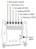
N and L are straightforward, they are the same for the Potterton and the Hive, so they simply transfer from one to the other, however, the link between L and 5 on the EP2001 does not need to be retained. This connection is made internally by the Hive so it doesn't have a terminal 5.

Earths from the EP2001 go to the Hive's earth tether.

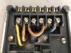
Then it is a matter of moving the remaining wires from the main switching terminals as defined on the back of your EP2001 (1, 3 & 4) as below


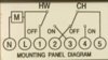
to the corresponding terminals at the Hive. Which is straightforward in this instance. [for example 'HW On' (EP2001) corresponds to 'Hot Water On' (Hive)] Even the numbers match up in this case. (lucky you!:))


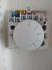
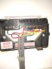
Because the Hive carries out the functions of the room thermostat as well as the EP2001 programmer, the old wired thermostat needs to be decommissioned to prevent it overriding the Hive. It can't simply be disconnected as this would leave the heating wiring 'open circuit' and it will not operate. The thermostat can be decommissioned in three ways, in order of professionalism, they are.

1. Find the origin of the cable going to the room thermostat. Note where the wires are connected and then disconnect the entire cable and remove it. Then insert a wire link between the terminals where the two switching wires (red and yellow) have just been removed from.

2. Remove the existing thermostat and replace it with a junction box, connect the two switching wires together (red and yellow) and isolate the neutral (blue)

3. Leave the existing room thermostat in place, and put both of the switching wires (red and yellow) in terminal 1.
 
@stem the op has double posted this and in his other post he says he had a new combi boiler fitted and is fitting a single channel hive
 
Indeed, I see the other post now, plus a third posting of it in 'Forum Information'. I found this one under 'unanswered threads' before looking in the P&CH forum. Obviously the previous one had already had replies so wasn't visible. I wonder why people do that when it wastes time & causes confusion, no wonder it's against the forum rules.... :rolleyes:
 
Sponsored Links
I'm really sorry that I caused confusion by posting twice . It was due to my confusion as a first time poster as to the process. The double post was an error. Thanks for the great advice and be assured that I will be more careful in the future. Sorry again
Regards Roger
 
Thanks for your understanding.
My hive is a single channel heating with a Honeywell t40 thermostat and gloworm cxi30 combi boiler. I have connected the neutral and live and heating on (4 ) from the potterton control to the hive neutral live and heating on(3) on the hive, joined the red and yellow on the existing thermostat. That leaves blue (1) and red (3) on the potterton redundant. The hive shows a solid green light but I am unable to get the boiler heating to fire up. Do you think that there is an open circuit somewhere. Any help is much appreciated
Regards Roger
 
as you have a new combi boiler, totally ignore all existing wiring, make sure that no connections have any power, site the receiver next to the boiler, remove all existing controls and wire as if a new installation, a short length of 5 core 0.75mm flex is all you need , it is very easy to do, but you need to disconnect everything else from your old controls
 
I would agree, best option is start from scratch, you have no idea where the wires that were originally used for domestic hot water go, however since you showed a programmer which did both domestic hot water and central heating I assumed a duel channel Hive, however since your not connecting up DHW you will likely be using a single channel Hive and the single channel is volt free so you will need a link.

a7ef87a0-cf51-4d1f-aeb5-93962c615527-jpeg.144132
So link L to 1 and you use 3 not 4 with single channel.
 
Ideally you should rewire it from scratch, as has been said. However you can replicate what the EP is doing now with regard to the central heating using a single channel Hive as follows:

Black wire in EP N = Hive Single Channel N

Red wire, plus one end of red loop in EP L = Hive Single Channel L

Other end of red loop = Hive Single Channel 1 (Common)

Yellow wire in EP 4 = Hive Single Channel 3 (Heating on)

The terminals EP 1 and EP 3 are for hot water control, so assuming that they are no longer used, because all your hot water comes direct from the combi boiler and you no longer have a hot water cylinder, the wires in them should be isolated / insulated and tucked safety out of the way. They should be 'dead' but can't say for certain without knowing what's on the other end of them.

Decommissioning the thermostat is the same for both versions of Hive. The thermostat can be decommissioned in three ways, in order of professionalism, they are.

1. Find the origin of the cable going to the room thermostat. Note where the wires are connected and then disconnect the entire cable and remove it. Then insert a wire link between the terminals where the two switching wires (red and yellow) have just been removed from.

2. Remove the existing thermostat and replace it with a junction box, connect the two switching wires together (red and yellow) and isolate the neutral (blue)

3. Leave the existing room thermostat in place, and put both of the switching wires (red and yellow) in terminal 1.
 
When replacing a control system with a Hive bear in mind the "hidden" diference between the Single Channel Hive and the Dual Channel Hive.

The Dual Channel does not have voltage free contacts.

0x56.jpg
 
Last edited:
Brilliant. The hive link from L to 1 (common ) did the trick thanks. Thank you for your patience and grear advice.
Regards Roger
 
My Existing Timer is a Landis & Gyr Type RWB100(see picture) do I just move the brown link wire from 2 to 1 and move the blue wire from 4 to 3???
Any help would be much appreciated,
Thanks.
 

Attachments

  • My Existing Timer Wiring  1.JPG
    My Existing Timer Wiring 1.JPG
    238.3 KB · Views: 244
Hi The Dillage

Welcome to the forum. Just a quick tip first, you should really have started your own new thread and not hijacked someone else's. It can get very confusing for others that follow, especially when your installation is nothing like the one originally being discussed.

Please familiarise yourself with the forum rules. (y)

Assuming that the existing RWB100 timeswitch is only controlling the central heating (and not the heating of any stored hot water) and also, that you have the single channel version of the Hive receiver, then yes the wire in 2 does go to 1, and the wire in 4 does go to 3.

If there is an existing separate room thermostat connected somewhere that will need to be decommissioned properly with a slight wiring modification, it can't just be disconnected.
 

DIYnot Local

Staff member

If you need to find a tradesperson to get your job done, please try our local search below, or if you are doing it yourself you can find suppliers local to you.

Select the supplier or trade you require, enter your location to begin your search.


Are you a trade or supplier? You can create your listing free at DIYnot Local

 
Sponsored Links
Back
Top