replacing a bathroom extractor fan

Joined
21 Sep 2010
Messages
28
Reaction score
1
Location
Fife
Country
United Kingdom
Hello awesome peeps,

I'm just looking for a quick bit of wiring advice.

I'm in the process of replacing a bathroom extractor fan with a different model, and I'm not quite sure how to wire it up (the manual it came with didn't have anything useful in this respect)

Below is a picture of the two units, with the old unit above and the newer one below. As you can see, my 'big grey cable' (sorry, I'm not good with correct terminology) has four smaller wires - grey, brown, black and something else, which currently just has a loose sleeve over it and it's connected to anything in the old unit.

The 'chocolate box' (I think that's the right terminology?!) in the new unit has four available 'slots', but I'm not sure what should go where. Also, the four available slots seem to be labelled '600v' and '450v', but I'm not sure how relevant that is.

I would be very grateful to receive any as to which slot I should connect my various wires. Thanks in advance :)

DSCN8536.JPG
 
Sponsored Links
What is written on the label under each connection on the existing fan. Does the new fan have any docuementation on the connections, the 450v and 600v markings are just ratings of the connector block
 
The grey cable is 3 core and earth - which on the old one are Live, Neutra, switch live and earth/cpc (not connected to anything. Is there anything that resembles similar in the manual? Can you post a photo of the wiring from the manual or state which make and model you bought?
 
The labels on the old fan are N (grey), L, (brown) LT (black) and then the unused one is L1.

The new fan is a 'Vortice Inline Extractor Fan 17021'

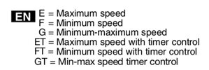
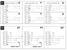
The diagrams in the manual are below -
Diagrams.jpg
 
  • Thanks
Reactions: CBW
Sponsored Links
You have a 7 strip, so it will be, imo one of the step 19 - just can’t work out which timer control you have.

Edit: Thanks to @EFLImpudence - the timer appears to be your option.
 

Attachments

  • 447661E6-935B-4B22-B48C-6B70627C9558.jpeg
    447661E6-935B-4B22-B48C-6B70627C9558.jpeg
    51.9 KB · Views: 20
  • 07395A80-7EA9-4D5B-BDD9-49E7D1105A2C.jpeg
    07395A80-7EA9-4D5B-BDD9-49E7D1105A2C.jpeg
    338.9 KB · Views: 25
EFL's photo above is spot on, just follow that. Just to explain the supply cable, the grey is the neutral, the brown is a permanent live (possibly via an isolator that is left on), the black is only live when the bathroom light is turned on. This then starts the fan and continues to run for a set time after the light has been turned off.
I assume you had that facility with the old fan?
The green and yellow wire is the CPC (earth). As there are no metal parts in the old fan, it has nowhere to connect to. It shows good workmanship the way it has been left in the terminal box, looks like a good spark wired it up.

The bathroom light is actually wired seperately. There's three switches for the room, one for the light, one for the fan, and one for the medicine cabinet which has lights of its own and a demister.
 

DIYnot Local

Staff member

If you need to find a tradesperson to get your job done, please try our local search below, or if you are doing it yourself you can find suppliers local to you.

Select the supplier or trade you require, enter your location to begin your search.


Are you a trade or supplier? You can create your listing free at DIYnot Local

 
Sponsored Links
Back
Top