- Joined
- 27 Nov 2017
- Messages
- 2
- Reaction score
- 0
- Country

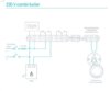
Hi Stem,
I have exactly the same set up as Dwag. just after a bit of confirmation. I seem to have some linked lives in my set up, see picture. Wire at bottom of photo is my fused spur live coming into the BDR91 (NL) no earths connected, but assuming BDR91 is double insulated). There is then a link live between the two Lives in the left block and another link across to A. Top wire from boiler live is linked to A (live) N to N (left block) and grey (Connection 4 internal (room thermostat) on Vaillant ecoTec). So assume this is heat call? So on NEST, Boiler L to L in Nest, Boiler N to N in Nest and grey to 3 in Nest? Fused Spur L & N to L&N in Nest. What's confusing me is the two wiring diagrams in the Nest manual see photos, one seems clear but on the specific 230v combi boiler diagram it looks like I need a link wire from the L in the Nest to connection 2 in the Nest? And the L from the boiler to 3, but this must be the grey heat call wire, musn't it?
Many thanks!
![IMG_0459[1].JPG](https://www.diynot.com/diy/data/attachments/131/131611-3387610bb406cde9a0238fca61106592.jpg?hash=M4dhC7QGze)