- Joined
- 24 Aug 2020
- Messages
- 4
- Reaction score
- 0
- Country

Hello experts.
I am trying to replace a faulty Immermat Flash mechanical timer switch with a Hortmann C17 digital switch.
The Immermat (which from my research I'm led to believe should have been for an immersion heater) is being used to switch on and off my heating (gas boiler). I do not have a Combi boiler as I have a hot water cylinder and a separate immersion heater. The gas boiler heats both my radiators and the water in the cylinder, I can isolate that to just heat the water in the cylinder by flipping a valve in the hot press.

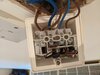
Below is the current wiring to the (now faulty) Immermat Flash that I want to replace.
My guess is that the extra wires are because the switch controls both the boiler and the pump that pumps fluid around the heating system to heat the radiators.

These are the terminals on the C17 (picture from the manual)

There are some wiring diagrams in the manual for the C17 but none of them match my set up.
(http://horstmann.securemeters.com/f..._guide_CentaurPlus_C11-C17_installer_web1.pdf)
Can anyone help me to determine how these 5 wires should be connected to the C17?
Thanks a lot.
I am trying to replace a faulty Immermat Flash mechanical timer switch with a Hortmann C17 digital switch.
The Immermat (which from my research I'm led to believe should have been for an immersion heater) is being used to switch on and off my heating (gas boiler). I do not have a Combi boiler as I have a hot water cylinder and a separate immersion heater. The gas boiler heats both my radiators and the water in the cylinder, I can isolate that to just heat the water in the cylinder by flipping a valve in the hot press.
Below is the current wiring to the (now faulty) Immermat Flash that I want to replace.
My guess is that the extra wires are because the switch controls both the boiler and the pump that pumps fluid around the heating system to heat the radiators.
These are the terminals on the C17 (picture from the manual)
There are some wiring diagrams in the manual for the C17 but none of them match my set up.
(http://horstmann.securemeters.com/f..._guide_CentaurPlus_C11-C17_installer_web1.pdf)
Can anyone help me to determine how these 5 wires should be connected to the C17?
Thanks a lot.