Seperate Hot Water to Heating control

Yellow - Cylinder
Grey - Valve
(No timer wire connected with these)
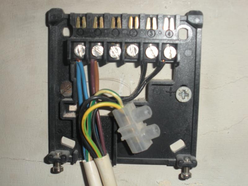
This cylinder connection is the SAT(isfied) terminal. The wire from timer HW OFF should connect to this terminal

Red - Cylinder
Black - Timer Controller
The red terminal is the thermostat common
The black is the timer HW ON terminal

Blue - Cylinder
Orange - Valve
Black - Boiler
Blue is cylinder stall CALL terminal
Orange is valve CH on wire
Black is live to Boiler

The wiring diagram shows there should be a live from the Pump connected to the blue,orange,black above but there isn't. The blue live from the pump is connected separately with the blue live's from the boiler and time controller.
Live is normally brown or red; blue is normally neutral. Are you sure the blue wires are live?

Some boilers have the pump connected directly to the boiler, so the boiler can control when it runs.

It sounds as if all you need is the connection from HW OFF to the cylinder yellow/valve grey. However, before you do this, please answer these questions.

Which make/model boiler do you have?
Which make/model timer do you have?
 
Sponsored Links
No not sure the blue are live, just thought they were for some reason, should know that really.

Boiler is a Potterton Profile 50el
Timer is Siemens RWB29
 
Boiler is a Potterton Profile 50el
That boiler has the pump connected directly to the boiler. The pump will have standard three core cable (L, N and E) the blue neutral and earth will probably be connected locally and the Live will go to a separate terminal on the junction box and from there to the Pump Live terminal on the boiler.

Timer is Siemens RWB29
Here are the Instructions

The HW OFF terminal is number 1.

You should check that dipswitch 5 is up (fully pumped).
 
What wire do I use to connect the timer to the SAT terminal. Also what are the chances of me blowing me or the central heating up if I do something wrong.
 
Sponsored Links
The Honeywell or similar 10 terminal wiring centre is just as good. Here is the wiring diagram

No it isn't. The Honeywell has no cable clamps, cover screws are too short and easily strip the thread, individual cable cut out slots and 10 crammed terminals (on S-Plan) mean a struggle to hold it all in place when first closing up unless using loads of nail clips.
 
What wire do I use to connect the timer to the SAT terminal. Also what are the chances of me blowing me or the central heating up if I do something wrong.
Do all the components connect into a junction box? If so, it would probably be better to replace the cable to the timer. You need a five core plus earth cable. B&Q sell it or any electrical wholesaler or plumbers merchant will have it. If you can't get this, you may have to use two cables, two core plus earth and three core plus earth; the earth wires may not be required. A 0.75mm cable will be OK.

If you do replace the complete cable, make sure you write down where both ends of each wire connect before removing the existing cable.

Turn the power off before doing anything and you will not blow yourself up!
 
Yep all go into a junction box. It sounds easy enough, I will give it a go at the weekend and let you know the outcome.
 
I know it has been a long time since the last post but for many reasons, mainly laziness, I have only just got round to trying to change the wiring. Back in May I was pretty sure that I knew what I was doing as it was simply a case of a missing wire to the HW OFF terminal, but now when I went to do it at the weekend I realised that I haven't got a clue.

I purchased the five core plus earth cable from B&Q as advised in the post of 21st May. Only problem is there is already a five core plus earth cable wired up to the backplate and I don't know if the additional five core cable is the correct route to follow to make the HW turn off in order to have seperate HW and CH, or if I should be using a different cable.

I have taken a photo of the backplate to show how it is currently wired. If the additional five core is needed, could you tell me how the wires should be put in the backplate and the junction box. If not, what wire is needed to complete the job.

Any advice much appreciated.

 
I purchased the five core plus earth cable from B&Q as advised in the post of 21st May. Only problem is there is already a five core plus earth cable wired up to the backplate and I don't know if the additional five core cable is the correct route to follow to make the HW turn off in order to have separate HW and CH, or if I should be using a different cable.
Got your comment ;)

There are two cable connected to the backplate. Do you know where the other end of these cable are? If so are the green/yellow earth wires also connected into a loose terminal block, i.e. not used?

If they are, you could use one of these wires as the connection from terminal 1 on the timer to the cylinder stat yellow/valve grey terminal. The wire in the right hand cable would be the most suitable as it appears to contain the two black wires connected to terminals 3 and 4.

If you do this, you should put some red insulating tape or sleeving round the wire at both ends to indicate that they are potentially live and not earth wires. The remaining earth wire should still stay in the terminal blocks for safety.

I don't normally recommend doing this as it's against the "rules". But there are times when it makes sense to break them. ;)

PS This way you won't need to use the 5-core cable. Return it to B&Q.
 
Have changed the wires and all seems to have worked, we now have seperate central heating and hot water control.

Many thanks D_Hailsham for your advice it is much appreciated.
 

DIYnot Local

Staff member

If you need to find a tradesperson to get your job done, please try our local search below, or if you are doing it yourself you can find suppliers local to you.

Select the supplier or trade you require, enter your location to begin your search.


Are you a trade or supplier? You can create your listing free at DIYnot Local

 
Sponsored Links
Back
Top