Should be simple? change inline smart switch

Joined
20 Jan 2023
Messages
28
Reaction score
0
Country
United Kingdom
Hi.
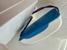
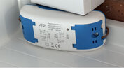
I have a Wiz (starlite) smart dimmer relay wired by an electrician that goes to a on off switch. Wiz are not making sense, they have updated the app so i cannot change the mode of the dimmer. originally it was on dimmer mode working great for years, soon as I reset it to change wifi , it has reverted back to ' on off' only mode

Wiz have deleted the old app so i cannot change the mode... So the simple option is to replace it, but I'm just wondering because the way this - it has a live and neutral In and a live and neutral out. I don't need to mess around with anything else but I'm just getting confused if this new one that I want, do I just wire the same. I think it's pretty straightforward, but I just don't want to take any risks.


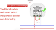
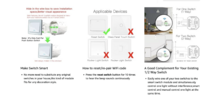
This is the one I want to use ( https://amzn.eu/d/i56gIhn ) but has 6 connections so which connections would I used...I have Live/neutral in and live/neutral out only going to Led all 230v

the link of old connector

Wiz not helping.
 

Attachments

  • IMG_9652.jpg
    IMG_9652.jpg
    109.6 KB · Views: 24
Last edited:
Ok , so I need to work out which side LIVE goes to the rocker switch then put that where the tick is

any chance u can break down exactly what I have to do as Im confused.
Should I just be looking for a dimmer module like this or is the one Ive linked ok?

this is the current item wired. 2 wires on left then 2 bottom right. thats it.


IMG_9672 2.jpg
 
So I just want to put LIVE/neutral in one side and same on the other...switch is wired behind all hidden.
So I'm just getting really confused. I just wanna keep all the wiring the same as this connector.
LIve/neutral input and Live neutral output... the rest of the wiring is already done behind it... like the Earth and the wiring to the rocker switch that's why I'm getting confused. I just need to know what type of module do I need so it can work like it did before where it turns non-smart bulbs into dimmable bulbs.
 
So I'm just getting really confused.
Not surprised, so am I, are you using low voltage (230) or extra low voltage (12) the problem has always been to get bulbs and dimmers that match each other.

Even in the days of tungsten, some of the coiled coils used as elements in bulbs could end up being a mini transmitter with power supplies which turned the 50 Hz to DC then back to AC in kHz range to transform it down to 12 volts, quartz halogen should not be dimmed, as the high temperature of the quartz is required, so the tungsten will not stick to it, and the compact fluorescent could not dim either, so all my dimming switched went.

The LED is a current dependent device, so it needs a driver, this is normally built into the bulb, and it can be as simple as a capacitor or a complex switch mode power supply, often all built into one chip. Extra low voltage bulbs can have drivers which allow them to give out the same light with 10 to 30 volts DC, using a switch mode power supply built in, others use a simple resistor.

However, the push for x lumens per watt, has go rid of many of the basic types.

So the devices need to talk to each other, the dimming switch tells the dimmable bulb or voltage/current dropper to reduce output, often by cutting the phase sine wave short, but if the output from the dropper, is in the kHz range, and square wave anyway, then the bulb can't see this as a command to dim.

So today we use bulbs with it all built into the bulb, that makes it simple, but not seen any 12 volt smart bulbs, I will guess they are made, but not available on the supermarket shelves.

For the bathroom, and garden pond, depending on location, we may need SELV (separated extra low voltage) but for most applications today low voltage (50 - 1000 volts AC) is OK, there is no advantage dropping from 230 to 12 volts. So the MR16 compatible lamp, does not need to be G5.3 and 12 volts, it can be GU10 and 230 volts.

As to dimming bulb or dimming switch, the bulb can change colour, to give a better ambiance to a simple dimming switch, Philips did make a special LED bulb which would go redder as it dimmed, but they cost about the same as a smart bulb, so have disappeared. But where one has 16 down lights, using a dimmer switch is often cheaper, but if using 16 lamps, why not split 6 and 10 giving three lighting levels without use of a dimmer?

So it seems like it or not, we are being pushed to the smart bulb. It's simple, fit a smart bulb, and it works, fit dimming switches, and you're left swapping bulbs until you find ones which will work without flicker, or flashing when turned off, or some other unwanted disco effect.
 
Yes, i see what you mean
In this situation the connector I am using does have the option of SELV... but I don't know if you can make it out in the picture. I am not actually using that because it was wired in by a professional ELECTRICIAN...
I'm using the 230 V option
so where the arrows are

It is 230v AC input on one side and 230v AC output on the other.. ALL bulbs are gu10 230v...No 12v being used here anywhere
So in essence, it's a live and neutral input from a normal UK power supply
and a live & neutral output from a normal UK power supply
The SELV section is not being used at all

Like I said, everything was working absolutely fine before when this connector was in dimming mode but unfortunately it's now stuck in on a relay mode only ( ON/ OFF )

As you can see in the manual, it does have a different modes... it's not possible to change these modes now because they have stopped updating the app for this function
https://assets.cef.co.uk/downloads/pdg/starlite_wzrtr2a_datasheet/starlite_wzrtr2a_datasheet.pdf

so I just need to know how to replace the connector. How to wire this ... I just want to replace the stupid thing with something exactly the same.
Thanks
 
Took the connector out..as we can see...2 wires in. 2 wires out...
 

Attachments

  • IMG_9680.jpg
    IMG_9680.jpg
    140.9 KB · Views: 17
If the switch being off kills power to the unit, it is on the input side. If it turns the light off but you can still hear the unit clicking when you turn it on and off with the app, it's output side (probably preferable for a wifi unit).

If I understand correctly you have a standard rocker switch for turning the light on and off but the dimming function is solely through the app?
If so you should be able to use the new unit by joining the 2 blue wires to Neutral, 1 brown to live in and 1 to live out. If the switch is on the input side, it may cause delays and lose the memory of its last dim setting as it'll be rebooting the electronics every time you switch.

Edited to add : it's possible you wouldn't hear any clicking either way, so you might just have to hope for the best. Make sure you isolate the power before doing any work.
 
Last edited:
The rocker switch kills the unit as I just tried to turn it off, the unit went offline so thats 100%.
Yes, app only dims the lights, (and through Alexa). I always leave the switch ' on ' so Im ok with it being ON all the time and using app only.

I'm sure I'm overthinking this, but I've just never looked at the unit until now.

Ok so...two blue wires I join together and put BOTH on the N (neutral terminal) on the new module.
When you say " 1 brown to live and 1 brown to live out'... which live exactly on the module as there are more than one.
Live wire to first screw and other live wire to third?
Thanks

EDIT if anybody has another model that is simpler... LINK would be great. I'm thinking if we could find a module that looks the same as the old one would make life a lot simpler but I can use the one in the picture if it would work.
 

Attachments

  • Screenshot 2025-11-04 at 20.33.31.png
    Screenshot 2025-11-04 at 20.33.31.png
    643.5 KB · Views: 16
Last edited:
Will try this and report back. Just trying to learn and save myself calling an electrician.
 
@ericmark I think the new unit proposed wiring allows a switch to be used but overridden in the app and vice versa. Because their current setup doesn't appear to be wired that way though, the switch will just kill the power to the unit.
 
Yes, current set up only has 2 wires input , 2 wires output, rocker switch is somehow wired to it but I dont know how as its hidden.
I just want to keep set up the same...ie just replace the unit in the same wiring map and got confused as new modules have different connection.

OK so
Switch is on the input side (as it kills unit when off) ...so
Join two neutral wires...put them in the neutral connection
Put one live wire to input (connection 1) then second live wire to output (connection 3)

Item coming this week so if this is right I will do this. The amazon listing just confuses me more.
appreciate the help.
 

Attachments

  • Screenshot 2025-11-05 at 12.48.56.png
    Screenshot 2025-11-05 at 12.48.56.png
    510.4 KB · Views: 15
Last edited:

If you need to find a tradesperson to get your job done, please try our local search below, or if you are doing it yourself you can find suppliers local to you.

Select the supplier or trade you require, enter your location to begin your search.


Are you a trade or supplier? You can create your listing free at DIYnot Local

 
Back
Top