
You are using an out of date browser. It may not display this or other websites correctly.
You should upgrade or use an alternative browser.
You should upgrade or use an alternative browser.
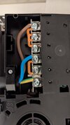
Should this be crimped?
- Thread starter dormermike
- Start date

D
Deleted member 142255
Personally I wouldn't call the guy an electrician.
I would either have used fork lugs, ring lugs or wrapped the conductors round the screw so they came back the other side.
I would also have left slack on the earth conductor so that in the event the cable gets pulled out, the earth is the last conductor, not the first to be pulled from it's terminal.
Nothing wrong with that
You need to leave room on the other side of the screw for the links
You need to leave room on the other side of the screw for the links
I would expect crimped lugs, or at least the wire to go around the screw, for better more secure contact. The earth wire, as mentioned above, ought to have been left longer, so it would be the last one to be pulled out, rather than the first to give. The flex doesn't look like 6mm, more like 2.5mm?
D
Deleted member 142255
Ahhh, you mean the link that is barely under the screw because the screw is now at an angle and has pushed it out?Nothing wrong with that
You need to leave room on the other side of the screw for the links
Two of the three links are on the wrong side, and the wires should have ferrules fitted.Should I redo this, or leave it?
Links and the wires should go on the left side of the screw only, which is why there is a tab there to stop the wire/link moving inwards when the screw is tightened.
I would either have used fork lugs, ring lugs or wrapped the conductors round the screw so they came back the other side.
Before crimp lugs, ferrules and etc., a good method was to form the flex into a full circle, then bind the two straight bits together, with thin fuse wire, forming a sort of banjo shape.
In my experience, having everything under the same side of the screw will force the screw to tip and leave the fixing insecure and a potential single point of contact/overheating, also the reality is those terminals are unlikely to have the capacity for a 6mm² ferrule, let alone a ferrule and a link in one side.Two of the three links are on the wrong side, and the wires should have ferrules fitted.
Links and the wires should go on the left side of the screw only, which is why there is a tab there to stop the wire/link moving inwards when the screw is tightened.
Excuse my crude sketch
Last edited:
That way the link maximises continuity. And what is the point of the tab if not as Flameport describes?Having everything under the same side of the screw will force the screw to tip and leave the fixing insecure, also the reality is those terminals are unlikely to have the capacity for a 6mm² ferrule, let alone a ferrule and a link in one side.
Excuse my crude sketchView attachment 371512
Sadly you are correctMost sparkies would do it like that,
I can only go by my experience of fixing the damage caused, the links are possibly self controlling by the length of the tines, however on the other side the action of the screw pushes the conductor out and therefore has the opposite issue.That way the link maximises continuity. And what is the point of the tab if not as Flameport describes?
With the tab there (which many similar terminals don't have) a ring crimp or wrapping the wire round the screw (unlikely yo be easy with 6mm²) are not ideal as it may result in an insecure fixing or cutting into the wire.
Last edited:
I can only go by my experience of fixing the damage caused, the links are possibly self controlling by the length of the tines, however on the other side the action of the screw pushes the conductor out and therefore has the opposite issue.
A work-around, without using crimps, is to strip a longer length of the insulation from the flex, and run the bared end, in the form of a U, around each of those screws. That way, the screw is not put under any side pressure, the flex makes direct contact with all three terminals, and the links can be discarded.
Agreed, as long as the wire isn't cut due to being pinched between the screwhead and the tab then yes I agree it would be a workable idea.A work-around, without using crimps, is to strip a longer length of the insulation from the flex, and run the bared end, in the form of a U, around each of those screws. That way, the screw is not put under any side pressure, the flex makes direct contact with all three terminals, and the links can be discarded.
As can be seen here
DIYnot Local
Staff member
If you need to find a tradesperson to get your job done, please try our local search below, or if you are doing it yourself you can find suppliers local to you.
Select the supplier or trade you require, enter your location to begin your search.
Please select a service and enter a location to continue...
Are you a trade or supplier? You can create your listing free at DIYnot Local
Similar threads
- Replies
- 6
- Views
- 5K