Siemens controller Vailant boiler wiring

Joined
16 May 2009
Messages
8
Reaction score
0
Location
Carmarthenshire
Country
United Kingdom
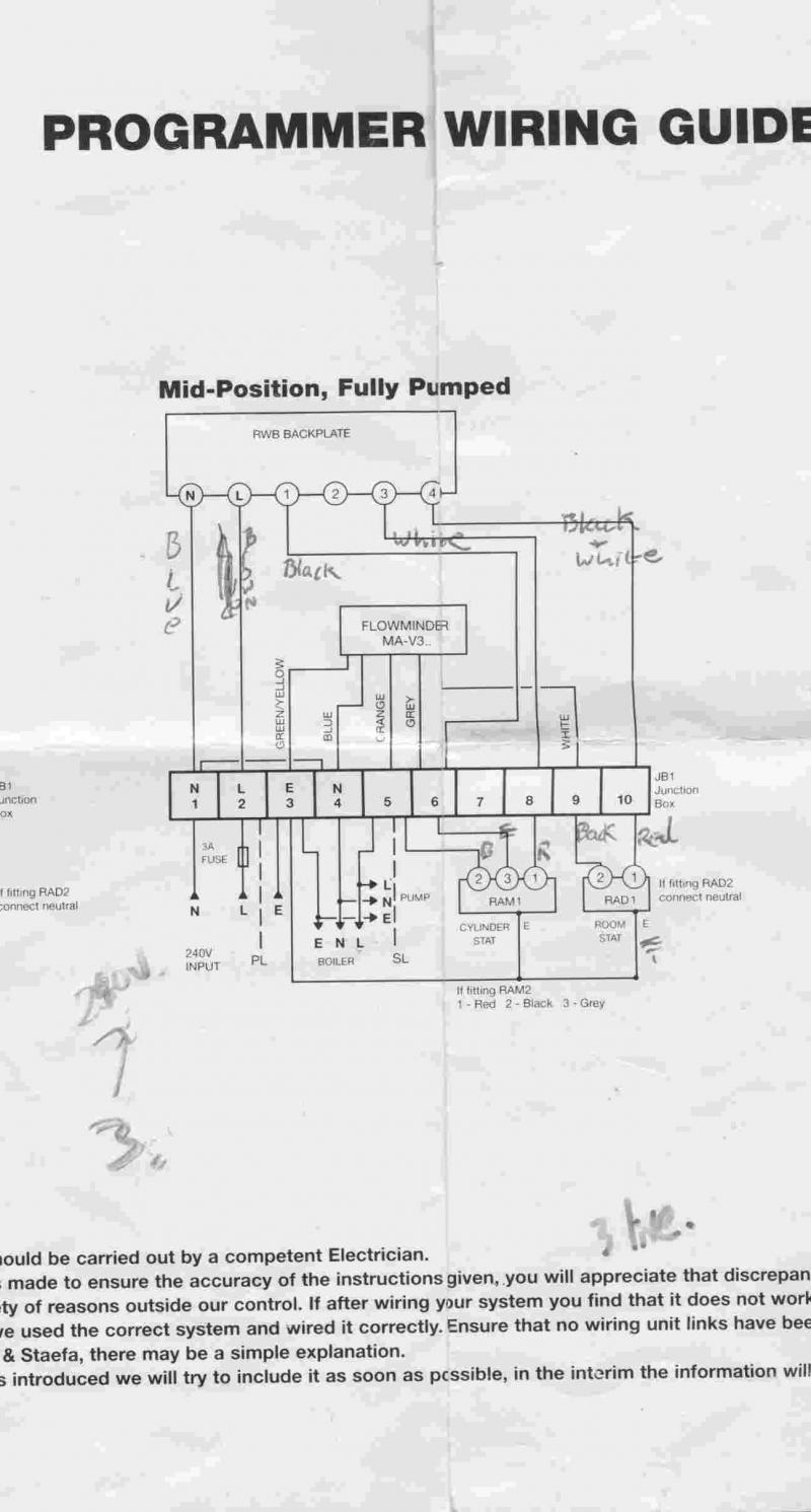
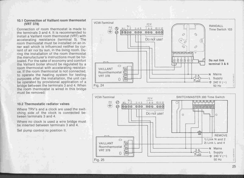
I've got a Vaillant VC GB 242 EH boiler and a Siemens RWB9 programmer, I've had problems with my system for a while with the diverter valve motor burning out, when I've checked voltages to the valve they seem to be wrong.

In order to figure this out I've gone through all the wiring again and all is well apart from the connection between the controller and the boiler.

I can't work out from the manufacturers diagrams (below)for these parts how the programmer should be connected to the boiler. it seems that connections 3,4 and 5 from the junction box should go to 3,4 and 5 on the boiler. Is that right, as different manufacturers do they have different wiring conventions.


I'd be very grateful for any assistance.

Thanks
Wynn
 
Sponsored Links
connect the wiring centre connection to boiler like this

wiring centre.................boiler

1....................................N

2....................................L

3....................................E

5...................................4

link 1 and 4 in wiring centre, ignore the instructions to connect L N E from 3 4 and 5 to boiler
 
Thanks for your reply Picasso, but I'm a bit confused by it. you say to connect 1 on the wiring centre to the live on the boiler and 2 to neutral. However the Siemens diagram has 1 as connected to mains neutral and 2 connected to mains mains live. Won't this cause a problem?

Thanks
Wynn
 
your vaillant boiler needs a permanent L N E and a switched live to turn the boiler on, the connections to 1,2 and 3 in the wiring centre are the permanent L N E to the boiler and the connection 5 in the wiring centre to 4 in the boiler is the switched live connection
 
Sponsored Links
your vaillant boiler needs a permanent L N E and a switched live to turn the boiler on, the connections to 1,2 and 3 in the wiring centre are the permanent L N E to the boiler and the connection 5 in the wiring centre to 4 in the boiler is the switched live connection
You are quoting the standard Honeywell Y Plan wiring terminal numbers. If you look at the diagram the OP has posted you will see that it shows: Terminal 1 = Neutral; Terminal 2 = Live.
 
my apologies, d hailsham is correct , please connect L to L and N to N wiring centre to boiler. I have edited my previous post to show the correct terminal numbers.
 
A word of caution here. Have been there before but I will say it again- If the (red) switch on the boiler is turned off (i.e. the boiler electrics are now isolated by the red switch), timer can apply 240 volts at terminal 4 making part of circuit live. This is the case for two channel programmer that takes 240 volt feed from L terminal internally. A single channel timer/ programmer has no volt contacts that can be used link 3 and 4 to run boiler.

Incidently, VC is a system boiler, not a combi which would be designated VCW
 

DIYnot Local

Staff member

If you need to find a tradesperson to get your job done, please try our local search below, or if you are doing it yourself you can find suppliers local to you.

Select the supplier or trade you require, enter your location to begin your search.


Are you a trade or supplier? You can create your listing free at DIYnot Local

 
Sponsored Links
Back
Top