Had a look at the garage light circuit. To be honest i cannot see much, the cable is cut very short inside the ceiling. The ceiling is entirely plasterboarded so i am unable to see the wiring directly.
It seems to be a 5 core cable - I could be mistaken here, it looks like 2 seperate red wires *but* it could be a single wire wrapped around itself.
2 black / 2 red and earth
2 black wires go into the lamp unit, this suprised me. I was expecting a live feed to be fed up to the light from the red/live in the dbl switch.
Would this indicate that the light circuit i marked up as "to garage light" actually goes to another lighting circuit / switch first before making its way onwards ??
This would not explain though, how my volt meter showed no voltage across the terminals L1 (black) and Common (red) on the garage switch.
If necessary i will lift the upstairs floor up though and take a peek
")
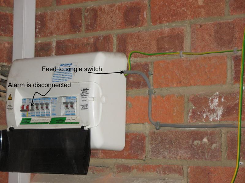
Shall I open the CU and take a look - most of the wires from the CU go into trunking and i *assumed* that the lighting ring would be inside there. I took a uneducated guess that the drilled hole in the top right of the CU (see pic i posted) was an extension to the lighting circuit...could it be the actual start of the circuit???
I am unable to post pictures as my card reader is kaput at the moment. Not that it would help much anyways, the wire is so far in the ceiling that all my attempts at lighting it resulted in severe over exposure. (guess i will x-post to a photography forum next)

Ps - Thanks for everyones help so far ... really appreciated.