Smart room thermostat

Joined
10 Feb 2019
Messages
16
Reaction score
0
Country
United Kingdom
want to remove Danfoss RMT230 and switch to using smart thermostat.

Any idea what the 2 and 3 pins connections do. See photo.
Using smart device as per instructions on left. It’s a zemismart room thermostat that works with Alexa operating wet underfloor heating servo valve.

How the heck does it wire up??
 

Attachments

  • D3B65922-75EA-4911-A66F-D2BD48F08C1F.jpeg
    D3B65922-75EA-4911-A66F-D2BD48F08C1F.jpeg
    163.8 KB · Views: 762
  • 5034DCB5-B80B-4C01-AE0B-0CEAD8CF7F8D.jpeg
    5034DCB5-B80B-4C01-AE0B-0CEAD8CF7F8D.jpeg
    192.7 KB · Views: 381
Sponsored Links
First of all this doesn't look like any RMT230 wiring I have seen

old.JPG


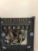
RMT230's usually look like this.

rmt 230.jpg


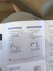
The diagram you posted shows two versions of the Zemismart thermostat, I assume you are referring to the diagram on the left as the one on the right is for electric underfloor heating. If so, the terminals are marked 1 & 2 are for a remote NTC (negative temperature coefficient) thermistor. If you don't need this facility, it can usually be selected out in the settings somewhere.

Not sure about 3 & 4, the instructions say "3/4 Connect to boiler pump" which is rather vague to say the least. If I had to guess I would say they may be a voltage free contact for a combi boiler......but hey who knows, do they not give any further information given about them anywhere?

The remaining terminals which may be the only ones you actually need, depending on how your system is presently wired / configured.

L and N are straight forward

NO is a 'Normally open' contact (used to provide a Live when the thermostat switches 'on' or is calling for heat)

NC is 'Normally closed' (used to provided a Live when the thermostat switches 'off' or is satisfied)

I have never installed one of these type of thermostats, which are not generally seen in the UK so would guess you have purchased it from a non UK website, such as a overseas Amazon site or similar. I am aware of a few folks in the UK who have had difficulties of one sort or another with similar thermostats. I don't know if they managed to get them working in the end or not.
 
Last edited:
Thanks for quick response.

I sent the photo from the actual installation.

I’ll double check the product number when I get in.

It shows L and N as you say is simple but it then has a jumper wire from live terminal to pin 2 and the grey wire to pin 3.
Pins 1 and 4 not used.
 
It’s actually this one.

Danfoss RET230VF2 Volt Free & 2 Led Indicators Room Thermostat 087N700801
 
Sponsored Links
That's more like it. In that case its terminals are as below:

Capture.JPG


From the above you can now work out what each of the existing wires does.

The Black wire in RET230VF N = Neutral
The Brown wire in 230VF L = Live
The Grey wire with brown sleeve in 230VF 3 = NC (Normally closed)

So you can now identify their equivalent connections at the new thermostat.

The link presently between L and C (Common) is present because the RET230VF has 'voltage free contacts' that can be used to switch any voltage. Not all thermostats have this provision and are only suitable for 230V so don't have a common terminal as they already have a link to 230v made internally.
 
So I presume I don’t need the link then???

And thanks again for your help
 
Because the link is to the live wire should the mains in wires be swapped over???
 
If the new thermostat doesn't have a 'C' terminal then there isn't anywhere to put it.
 
Because the link is to the live wire should the mains in wires be swapped over???
Sorry I don't understand that. But don't swap L & N over.:eek:

If I explain the theory it might help. All thermostats have a simple electrical switch inside that switch the heating 'on' and 'off'. With some thermostats, the supply to the switch is internally linked inside the device to the Live terminal. With other thermostats this link is not made internally and is instead wired to a connection terminal outside marked 'C' (Common) as is the case with your existing thermostat. This contact is referred to as 'voltage free' so that it can be used with any voltage (some boilers use 24v for their control circuits) If you want to use a thermostat to control a 230V heating system and are using a voltage free contact, one side of the the contact (the C terminal) must be linked to the Live supply. Alternatively, with a thermostat that already has the link to 230V is made internally, no external link is required and no 'C' terminal is provided.
 
So pin 5 is grey wire. NC....
Don’t use link anywhere!!
7 is live and 8 neutral


That’s right yes???
 
Looks right to me. From your photo of the backplate and the wiring diagram for your existing thermostat the wires are currently identified as being connected as follows:

The Black wire = Neutral
The Brown wire = Live
The Grey wire with brown sleeve = NC

The same connections at the new thermostat would be:

Capture.JPG


It's slightly unusual to use NC (most systems use NO) to control the heating but that's how it is now, so you will be swapping like for like.
 
Just about to connect up but did a double- take on the origional. Isn’t pin 3 for NO ( normally open) as you suggest modern systems are. If so it’s pin 6 on new one not 5.
 
Are you looking at different pictures to me? If you look at your photo below, the grey wire is presently in terminal 3, which you can also see underneath is definitely NC according to the manufacturers diagram for the RET230VF.

You can also see that terminal 4 which is NO is not connected to anything. So if your heating system is working as it should be now, and you haven't said that it isn't, then you shouldn't change anything. You are just swapping the wires over from one thermostat to another thermostat like for like.


Capture.JPG


DIA.JPG


If is unusual, but if it were connected the wrong way around for your heating system's configuration, it would presently be working in reverse. Meaning that the heating would be 'on' when it really should be 'off' and vice versa.
 
I was viewing this.i guess if it’s wrong way round it shouldn’t cause any issues. Just not work correct and I could change round later.

But the circuit diagram I sent you for the device just shows that it’s connected at present to pin 3 ( in thumbnail that is NO)
 

Attachments

  • 885F25B8-5A0F-4D93-AC60-0FC2BEED0925.png
    885F25B8-5A0F-4D93-AC60-0FC2BEED0925.png
    102.5 KB · Views: 371

DIYnot Local

Staff member

If you need to find a tradesperson to get your job done, please try our local search below, or if you are doing it yourself you can find suppliers local to you.

Select the supplier or trade you require, enter your location to begin your search.


Are you a trade or supplier? You can create your listing free at DIYnot Local

 
Sponsored Links
Back
Top