• Looking for a smarter way to manage your heating this winter? We’ve been testing the new Aqara Radiator Thermostat W600 to see how quiet, accurate and easy it is to use around the home. Click here read our review.

Socket cables in insulation

Joined
29 Feb 2024
Messages
16
Reaction score
0
Country
United Kingdom
Hello,

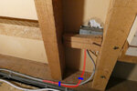
I am fitting 75mm PIR insulation behind a plasterboard wall in a bedroom in a chalet bungalow. There are a couple of sockets I need to work around and am unsure about how to route the cables so I can fit the insulation. I have a photo showing the current cable routing and proposed changes.

Shown as a red line is my plan of re-laying the cable. It exits the backbox at the bottom and will run against the wall and then be clipped (shown in blue) on the top surface of the timber and then clipped again on the side of the timber. Is there a limit to how much I can bend twin and earth cable?

Thanks for your help.
 

Attachments

  • Cabling route 1.JPG
    Cabling route 1.JPG
    131.8 KB · Views: 65
Last edited:
Where are you standing in that photo? i.e. you're looking at the timbers of a stud wall, and the reverse side of the plasterboard of the bedroom wall?

Is where you are unheated? What happens if you just don't bother with insulation in that small area under the noggin the socket is fixed to?

I know that insulation affects how much current a cable can carry - I wonder if anyone can advise on whether you could just tack a bit of ply to the vertical timbers and squirt expanding foam into the space?
 
Where are you standing in that photo? i.e. you're looking at the timbers of a stud wall, and the reverse side of the plasterboard of the bedroom wall?
As it's a chalet bungalow, there are storage areas on each side of the house accessible via a hatch in the wall, so I am behind the bedroom wall.
Is where you are unheated? What happens if you just don't bother with insulation in that small area under the noggin the socket is fixed to?
It is unheated. The difference in temperature between this storage area and and bedroom is between 2 or 3 degrees throughout the year. I will be adding insulation to the wall (shown in red) and between the floor joists (shown in purple) so the temperature difference will increase, particularly if I remove the original insulation that is currently between the roof joists (shown in green).

Proposed insulation__________Current insulation
Image2.jpg Image4.jpg

There are other sockets to negotiate to.

Socket 2.JPG Socket 3.JPG

What happen if I leave gaps in the insulation? I've gone to the expense of buying Gapotape, so I'd rather not have large gaps. To what extent this will affect insulation properties is unclear.

I know that insulation affects how much current a cable can carry - I wonder if anyone can advise on whether you could just tack a bit of ply to the vertical timbers and squirt expanding foam into the space?

Does foam not have the same insulating properties?

I assume this is a common problem to encounter nowadays. :unsure:
 
Last edited:
Would it be okay if I drilled a hole in the 75mm PIR and just fed the cable through into the back of the back box?
 
Would it be okay if I drilled a hole in the 75mm PIR and just fed the cable through into the back of the back box?
Yes.


Although, if you install the cables touching the plasterboard or studs and just cover them with the insulation that would be alright as well.
 
VoidInsulationPlan.jpg

This is a photo of the ceiling-floor void that I will be plugging with PIR insulation. In some of these sections there are cables running down the joists. Some are 1.5mm for light fittings, some are 2.5mm for the ring and on one section there is 6mm for the cooker circuit. I will be cutting a hole on the side of the insulation so the cables are able to dissipate heat, but how large should the holes be? The PIR is 75mm thick.

Could I put flexible split conduit over the cables and then make a hole in the side of the insulation that fits around the conduit? If this is a good idea what diameter should the conduit be?
 
I think you are probably OK but we need to check the cooker circuit.

View attachment 398694

This is a photo of the ceiling-floor void that I will be plugging with PIR insulation. In some of these sections there are cables running down the joists.

Look up “cable installation reference methods” and find some diagrams.

What you have currently is “method C”, “clipped direct”. When you add the insulation it will become one of the “10X” methods. Which one depends on what the cable is in contact with and the amount of insulation. The combination of the installation method and the cable size determines the current-carrying capacity.

Some are 1.5mm for light fittings, some are 2.5mm for the ring and on one section there is 6mm for the cooker circuit.

Generally, lighting circuits - protected with a 6A MCB and any cable size - can be installed using any of the methods and have sufficient capacity.

Socket ring circuits in 2.5mm can only be installed with methods 100 and 102.

What rating MCB does your 6mm cooker circuit have?

I will be cutting a hole on the side of the insulation so the cables are able to dissipate heat, but how large should the holes be?

They dissipate heat by conduction into the wood that they are clipped to. No need for any specific hole size.


Could I put flexible split conduit over the cables and then make a hole in the side of the insulation that fits around the conduit?

I don’t think you want to do that; it’s reducing the contact between the cable and the wood. I believe it is “method A”, though that may depend on the thickness of the insulation.
 
What rating MCB does your 6mm cooker circuit have?
1.5mm Lighting circuit 5A fuse, 2.5mm Socket ring 30A fuse and 6mm Cooker circuit 30A fuse.

It's tricky interpreting those methods in relation to this application. My understanding is that the gap between the cable and the PIR is not relevant although it shouldn't touch, but the cables need to remain clipped to the joist.

6mm cable routing 1.jpg
Because of the way the 6mm cable is bent as it routes under the floor towards the kitchen, the cable has no clip at the point where I want to place the insulation. Is this okay, as the cable isn't flat enough against the timber to clip at that point.
 
1.5mm Lighting circuit 5A fuse, 2.5mm Socket ring 30A fuse and 6mm Cooker circuit 30A fuse.

Fuses in 2025 !? Upgrade soon. Do you have an RCD?

Are they re-wireable fuses, i.e. you can fix them with fusewire, or are they cartridges, somewhat like appliance plug fuses?

30A fuse with 6mm cable can be installed by methods 100 and 102 only if you have a cartridge fuse, not a rewirable fuse.

It's tricky interpreting those methods in relation to this application. My understanding is that the gap between the cable and the PIR is not relevant although it shouldn't touch, but the cables need to remain clipped to the joist.

Yes they should remain clipped.

View attachment 398856
Because of the way the 6mm cable is bent as it routes under the floor towards the kitchen, the cable has no clip at the point where I want to place the insulation. Is this okay, as the cable isn't flat enough against the timber to clip at that point.

Probably OK as long as it isn’t surrounded by insulation.
 
Fuses in 2025 !? Upgrade soon. Do you have an RCD?
No RCD. It's the original 1970's wiring.

The cables to the sockets and switches are all in conduit in the walls. The plan is for me to replace the cables and accessories section by section, apart from the final legs to the fuse board and then get an electrician to replace the fuse board with a consumer unit.

Are they re-wireable fuses, i.e. you can fix them with fusewire, or are they cartridges, somewhat like appliance plug fuses?
They are re-wireable, original Wylex fuses and board.

Probably OK as long as it isn’t surrounded by insulation.
Is it considered surrounded in this instance if the PIR is not touching it?

Thanks for your help.
 
No RCD. It's the original 1970's wiring.

The cables to the sockets and switches are all in conduit in the walls. The plan is for me to replace the cables and accessories section by section, apart from the final legs to the fuse board and then get an electrician to replace the fuse board with a consumer unit.

Wrong order. Replace the consumer unit first. Then you’ll be protected by the RCD while you do the other works.

Is there anything wrong with the conduit wiring? Any significant rust or other problems? No need to replace it otherwise.

(I live in a similar property, with singles in conduit installed in 1980. When I moved here there was a consumer unit with MCBs and no RCD - presumably replacing an earlier fuse box. Replacing that with RCBOs, and getting measurements for the circuits, was one of the first things that I did.)

They are re-wireable, original Wylex fuses and board.

So as noted, you cannot insulate near the cooker cable.
 
Wrong order. Replace the consumer unit first. Then you’ll be protected by the RCD while you do the other works.
Okay, fair enough.

Is there anything wrong with the conduit wiring? Any significant rust or other problems? No need to replace it otherwise.
I haven't noticed anything wrong with the wiring, no rust or green stuff, it seems to be in good condition. There hasn't been any electrical issues in the last 30 years.
(I live in a similar property, with singles in conduit installed in 1980. When I moved here there was a consumer unit with MCBs and no RCD - presumably replacing an earlier fuse box. Replacing that with RCBOs, and getting measurements for the circuits, was one of the first things that I did.)
I can see that some of the cable clips have broken and when using strippers on a lighting cable it was stripping both the outer and inner sheath at the same time, presumably because the PVC is past it's best.

I assumed that any electrician sent to replace the fuse board would just insist on a re-wire considering it's a 70s install.
So as noted, you cannot insulate near the cooker cable.
Okay. So, with a new consumer unit and RCBO the insulation would just need a gap large enough for the cable to pass?
 
What would be the process of fitting a new consumer unit? Would there be an EICR first? If so I should probably trace the lighting circuit and its junction boxes and tighten the terminals, so I don’t have to pay for more of the electrician’s time.
 

If you need to find a tradesperson to get your job done, please try our local search below, or if you are doing it yourself you can find suppliers local to you.

Select the supplier or trade you require, enter your location to begin your search.


Are you a trade or supplier? You can create your listing free at DIYnot Local

 
Back
Top