Sunvic Valve Body Question

Joined
16 Mar 2019
Messages
24
Reaction score
1
Country
United Kingdom
Slightly strange question!

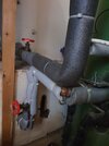
Got up yesterday morning and no hot water, the system has a hot water tank and two Sunvic 2 port motorised valves, 1 for the radiators, the other for the coil in the hot water tank.

I went through the usual checks and am satisfied that the controls and boiler are all working correctly, as are both valve actuator heads. However even when the hot water actuator head is manually set to "flushing" position there was no flow to the tank coil.

I removed the actuator and was able to turn the valve spindle manually, it was slightly sticky but could be moved using only my fingers, still no flow when set to the open position though.

Here's the question,
Is it likely/possible that the valves internal "shoe" is stuck and the spindle has become detached from the spindle?

The valve is at least twenty years old!

Thanks in advance Guys :)
 
Sponsored Links
When you opened the HW valve manually and/or removed the actuator and turned the spindle by hand, did you get the boiler to fire by requesting CH on?
 
Last edited:
Thanks for your response John :giggle:
I did indeed get the boiler to fire.
The radiators etc all work fine but I have no flow through the hot water valve to the tank coil in any usage configuration,
Hot water only = boiler fires but no flow to tank coil
Radiators only = ditto
Hot Water & Radiators together = ditto
 
Could be the ball/shoe so, some coils have a balancing gate valve on the coil outlet, if so, check by closing/opening again, also very remote possibility that air is trapped in the coil flow side.
 
Sponsored Links
Does it get hot at the valve inlet?
 
There are 2 gate valves to my tank coil,
Assuming that the motorised valve is in the flow line (it's the lower of the two connections) it goes thus,
Gate valve
Motorised valve
Coil
Gate valve

As far as I am aware both gate valves are and always have been fully open.

If there is air trapped in the coil flow side, how do I go about purging it?

Thanks again.
Can you post a photo of that set up?, normally, the M.valve is on the coil top entry, the gate valve is then on the coil return.
 
Can you post a photo of that set up?, normally, the M.valve is on the coil top entry, the gate valve is then on the coil return.
There it is, the valve actuator mounting plate is middle right, both gate valves on the left, out of shot at the top is an Auto Air Valve, also out of shot is piping to the other coil which is for the Thermal Solar heating (long since switched off!)
 

Attachments

  • FB_IMG_1676210323354.jpg
    FB_IMG_1676210323354.jpg
    217.3 KB · Views: 39
Normally, when a solar system is decommissioned, the two coils might then be combined (either in parallel or series), the two red gate valves might be the flow&return from the solar coil, so still not sure what is or isnt combined, if the motorized valve is the HW zone valve then the only way that this could work is that only the solar (bottom) coil is now being used, the hot water enters (where the AAV is) via the top gate valve and exits via the bottom one and then the M.valve, still a bit confusing because with two coils then there are 4 connections whether utilised or not, can you clarify this?.
 
The Solar Thermal has been switched off for about 8 years now, just that, switched off, no other attempts have been made to decommission it, the solar collector is still connected to the tank via it's own separate coil.
The hot water has been OK up until yesterday.

The Boiler Coil is as you see it and it's various valves etc in the picture.

There are 4 coil connections, flow & return for the solar, these are at the bottom. And flow & return for the boiler about 1/3 up.

Plus of course, at the top, cold water input and hot water output.
 
Are these the two gate valves you are referring to and is the M.valve about 1/2 way between the two and to the right with actuator removed and seems to be on the same pipe as the bottom gate valve??. OR is the water only passing through one of these gate valves and the actuator is somewhere else? or can you just draw it out on a bit of paper showing AAV etc.

Or is it M.valve, gate valve, Coil, gate valve then up to the AAV. If try and get air/water from the AAV thhere is normally a cap on top, also close/open the two gate valves fully, 3 to 5 full turns each to ensure fully open

You said
"There are 2 gate valves to my tank coil,
Assuming that the motorised valve is in the flow line (it's the lower of the two connections) it goes thus,
Gate valve
Motorised valve
Coil
Gate valve"

1676215471609.png
 
Last edited:
Gate valve (bottom left)
To Motorised Valve (actuator mounting plate visible middle right)
into coil
out of coil
to T joint (up to AAV, flow towards gate valve)
Gate Valve (middle left)

All assuming that the flow does go GV MV COIL (AAV) GV, I don't know for sure ;)
 
OK thanks, its clear now, if no compression fittings anywhere then shut the two gate valves and you may be able to slacken/remove the mounting plate with valve and inspect it if it seems OK, flush the coil from both sides to prove clear, if compression fittings at the valves then you can remove and flush both ways to prove valve clear maybe. If you had HW yesterday then definitely points to ball/shoe problem.
 

DIYnot Local

Staff member

If you need to find a tradesperson to get your job done, please try our local search below, or if you are doing it yourself you can find suppliers local to you.

Select the supplier or trade you require, enter your location to begin your search.


Are you a trade or supplier? You can create your listing free at DIYnot Local

 
Sponsored Links
Back
Top