
You are using an out of date browser. It may not display this or other websites correctly.
You should upgrade or use an alternative browser.
You should upgrade or use an alternative browser.
Thermostat
- Thread starter Tomo72
- Start date

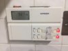
So, this is what I’ve got in the existing thermostat. Doesn’t that make it a 240V? If I were to use a battery operated thermostat, I’d just use two wires? Which ones? Would this do the job?
https://www.amazon.co.uk/dip/B074M8RV45/ref=cm_sw_r_sms_c_api_Si62zb8SYHSD9
Yes it's 230V
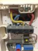
1 Red is the live from the existing timeswitch [to be a permanent live if you set the programmer to 'heating permanently on']
2 Yellow is the switched live to control the heating
4 Blue is the neutral
If you use a battery operated programmable thermostat with a potential free switch then 1 & 2 are the wires that would go to the contacts. You don't need the neutral it can be isolated and tucked out of the way.
If you do go for a programmable thermostat and leave the existing timeswitch so that the heating is permanently on, then you have a permanent 230v mains supply at the thermostat which would allow you to use a mains powered thermostat instead of a battery powered one. The red and blue wires providing the 230v supply
Edit
I think our last posts crossed in the ether. But I think I have answered it. If you go for a programmable stat You can use a 230v stat or one that is battery operated and has voltage free contacts.
How does my current thermostat work, does it just link like a switch something in the boiler or does it feed back 240V to the boiler?
Yes it is a switch, but you haven't told us much about the system your boiler is connected to, so I am assuming that it either has a single 3 port motorised valve, or two, 2 port motorised valves controlling it. If so, the thermostat will be wired to the motorised valve controlling the heating. In turn, inside the motorised valve will be a microswitch that actually provides switching control of the boiler.
If you have something different please post back what you have.
Yes it is a switch, but you haven't told us much about the system your boiler is connected to, so I am assuming that it either has a single 3 port motorised valve, or two, 2 port motorised valves controlling it. If so, the thermostat will be wired to the motorised valve controlling the heating. In turn, inside the motorised valve will be a microswitch that actually provides control of the boiler.
Thank you for your detailed descriptions, answers and help thus far Stem. It is indeed a single motorised valve in the airing cupboard. In this case, would the Floureon one I first linked be ok to use?
Not really, as we are back to the underfloor sensor problem. There maybe a fudge out there that will allow you to by-pass it, such as inserting a resistor across the terminals to give it a fake reading, but I am not able to advise you about that.
However, as far as control goes it is still classified as boiler control. [Remember the instructions "Not fit..... water boiler"] The microswitch in the motorised valve only acts as an isolating device, so that the heating thermostat doesn't also turn on the hot water and vice versa.
However, as far as control goes it is still classified as boiler control. [Remember the instructions "Not fit..... water boiler"] The microswitch in the motorised valve only acts as an isolating device, so that the heating thermostat doesn't also turn on the hot water and vice versa.
The Floureon thermostat has a built in sensor as well as an extra external sensor that is optional. If I tried to use this and make it work it has 4 connections, 240AC in and 240AC out. Would simply connecting the live out only wire be ok or linking the two neutrals get around this or is that a big no no and I should forget about that one and look more at this one
https://www.amazon.co.uk/dp/B074M8RV45/ref=cm_sw_r_sms_c_api_Si62zb8SYHSD9?tag=diynotcom-21
https://www.amazon.co.uk/dp/B074M8RV45/ref=cm_sw_r_sms_c_api_Si62zb8SYHSD9?tag=diynotcom-21

")
Like I said, I can't really comment on the Floureon workings. If it was suitable for wet central heating, then I would have expected them to say so, and sell more thermostats rather than say it's for electric underfloor heating and not suitable for systems with a boiler.
It does say the floor sensor is optional, so in theory, reading the spec, I would reason like you that if it is just a switch is capable of switching 12A that would mean that it should be well capable of switching less than 1A. Then I wondered if it regulates the output somehow instead of simply switching it on and off, so that the temperature of surface of the floor drops rather than goes completely cold. If it did vary the output that would make it unsuitable for other applications. I just don't know anything about this product to be able to advise you.
Electrically speaking the three wires you have would allow you to use it. You wouldn't connect anything to the neutral 'load' terminal, There isn't a neutral 'load' connection at your existing thermostat so your motorised valve will already be picking this up from somewhere else.....whether it would work or not is of course another matter.....
Thanks very much Stem, exactly my thoughts late last night/this morning. I'm going to purchase a battery operated volt/potential free one and take it from there.
So, this is what I’ve got in the existing thermostat. Doesn’t that make it a 240V? If I were to use a battery operated thermostat, I’d just use two wires? Which ones? Would this do the job?
https://www.amazon.co.uk/dip/B074M8RV45/ref=cm_sw_r_sms_c_api_Si62zb8SYHSD9
Hi All,
So I ordered this https://www.amazon.co.uk/dp/B074M8RV45/ref=cm_sw_r_sms_c_api_Si62zb8SYHSD9?tag=diynotcom-21 and it arrived today. So, now the wiring;
Blue - leave disconnected and isolate it
Red - COM
Yellow - NO (normally open)
Is that correct?
Attachments
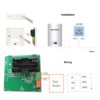
Ah well that depends what the other ends are connected to, which would have been up to the personal preferences of the original installer. Normally (about 95% of them) are wired as below, in which case what you say is correct. But you do find the odd rogue installation.
1. Red - live supply
2. Yellow - Switched live that controls the heating
3. Blue - Neutral
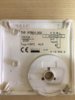
There are two ways to check for certain. One is to test them with a multimeter, and the other is to identify what they do from the terminals they connect to at the existing Potterton thermostat. Unfortunately I don't have the diagram or instructions for it to know for certain what 1 ,2 & 4 correspond to. Is there a wiring diagram in the lid?
1. Red - live supply
2. Yellow - Switched live that controls the heating
3. Blue - Neutral
There are two ways to check for certain. One is to test them with a multimeter, and the other is to identify what they do from the terminals they connect to at the existing Potterton thermostat. Unfortunately I don't have the diagram or instructions for it to know for certain what 1 ,2 & 4 correspond to. Is there a wiring diagram in the lid?
Thanks, then you can proceed as you thought.
Hi All,
So I ordered this https://www.amazon.co.uk/dp/B074M8RV45/ref=cm_sw_r_sms_c_api_Si62zb8SYHSD9?tag=diynotcom-21 and it arrived today. So, now the wiring;
Blue - leave disconnected and isolate it
Red - COM
Yellow - NO (normally open)
Is that correct?
Thanks, then you can proceed as you thought.
Many thanks for your help stem.
DIYnot Local
Staff member
If you need to find a tradesperson to get your job done, please try our local search below, or if you are doing it yourself you can find suppliers local to you.
Select the supplier or trade you require, enter your location to begin your search.
Please select a service and enter a location to continue...
Are you a trade or supplier? You can create your listing free at DIYnot Local
Similar threads
- Replies
- 3
- Views
- 3K
- Replies
- 4
- Views
- 8K
- Replies
- 2
- Views
- 3K