Timer, boiler and stat wiring

Joined
1 Feb 2015
Messages
4
Reaction score
1
Location
Sussex
Country
United Kingdom
Hi
I have a Worcester Greenstar 28i Junior boiler, Drayton LP111 and a Drayton RTS8 room stat.
Water is on the combo boiler and is fine. Heating is the issue.
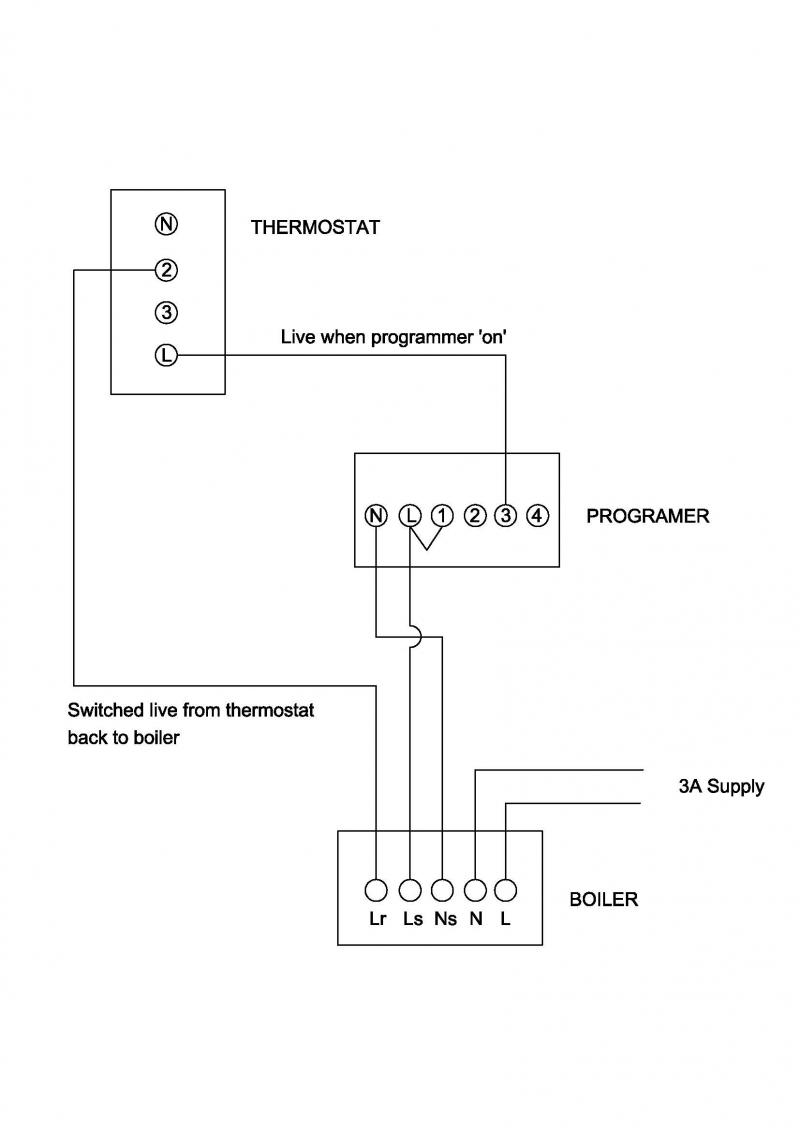
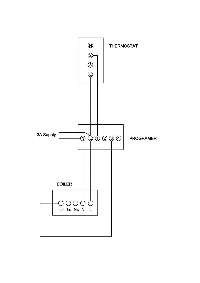
Wiring is as follows:- from fused switch there is a live neutral and earth into their normal positions. There's also a live and return from the stat. This is wired into positions one and three on the LP111
The stat is wired into the live and position 2. Per the instructions.
There is also wiring going back to the boiler, live, neutral and earth connected to the same connections as the main switch. Plus two other wires. I know not where they go. I also doubt the connections to the stat.

Any ideas where I can start? Currently off is on and timed function are reversed and on is off.
 
Sponsored Links
Hi Simon, and welcome to the forum.

This is what I would expect to find.


The programmer gives a live out on terminal 3 which supplies the thermostat L. Then, a switched live from the thermostat goes back to Lr (Live Return) to operate the boiler.

But you say
There's also a live and return from the stat. This is wired into positions one and three on the LP111
That is incorrect the thermostat and programmer contacts are actually wired in parallel, they should be in series, so that both have to be 'on' for the boiler to operate. But has it never worked properly? Has something been changed recently?

We also have...
There is also wiring going back to the boiler, live, neutral and earth connected to the same connections as the main switch. Plus two other wires. I know not where they go.
As you don't give any details of these, I can't determine what they are or what they do. It is possible that the wires in question may be connected to a frost thermostat somewhere (loft / garage) If so, this will override the programmer and turn the heating on when it's approaching freezing, so could explain it being 'on when the programmer is 'off', but it doesn't explain it being 'off' when it should be 'on'. On the other hand, it may be entirely unrelated. I once found a TV signal amplifier wired into a boilers electrical supply!
 
Stem,

Thanks for your reply, let me clarify what I know, relative to your diagram.

The link between L and terminal one in the programmer is missing, the Worcester instructions seem to suggest it should be in certain applications but I'm unsure as to my installation requiring it or not. However, when fitting a new stat yesterday, I placed a meter across L and 2 at the stat and could measure a current as it suggested. LP111 instructions say that the connections are volt free, so I guess, I need the link and wont measure the current at the stat without it. Easy if you think about it I guess?

It "appears" in my installation that the programmer seems to be used as a junction box too. Rightly or wrongly I couldnt say.

Presently, the 3A supply that you draw fed to the boiler, joins the N, E and L supply wires AT the programmer, so the 3A supply N and L feeds are direct to the Programmer N and L.
Will this completely bypass the function of the programmer and the stat?
Does it not need a constant (unswitched) N and L to operate in HOT WATER mode as a combi boiler. (There is not switching function for HW on the LP111, this only switches the CW)

A bit of the property history, it is a "council" dwelling and my girlfriend has recently moved in. I think the LP111 mave have recently been moved, hence the wiring being all over the place.

Is the connections for the boiler in the depth of the machine as I cannot see it at all?

I note your comment about the frost stat. I dont think there is a remote one, but on the front of the boiler there is a rotary switch that seems to control the temperature somehow. This could just be an internal boiler stat.

Thanks again for your reply. I look forward to the next.
 
The link between L and terminal one in the programmer is missing, the Worcester instructions seem to suggest it should be in certain applications but I'm unsure as to my installation requiring it or not.
The programmer will need a mains supply to switch from somewhere. If the link is missing, that suggests that the permanent live goes to the thermostat first and then back through the programmer, if so, the link is not required. This is a slightly unusual way of wiring it, but it's OK.

It "appears" in my installation that the programmer seems to be used as a junction box too. Rightly or wrongly I couldnt say.
That's pretty normal in a fairly simple installation like this.

Presently, the 3A supply that you draw fed to the boiler, joins the N, E and L supply wires AT the programmer, so the 3A supply N and L feeds are direct to the Programmer N and L.
Also OK, if as shown in my revised drawing below. The Ls and Ns terminals are there for the installers convenience, they don't have to be used.

Based on your clarifications here's my revised understanding of how I think it should be. How does this correspond to what you have? (the wires at the programmer terminals 1 & 3 can be either way around, it doesn't matter they are just a switch) You will notice the thermostat is connected to L and one of the switch terminals at the programer. Not, both switch terminals (1 and 3) as you state in your original post.


Does it not need a constant (unswitched) N and L to operate in HOT WATER mode as a combi boiler.
Yes it does that is why there should be permanent supply to the boiler terminals N & L. Control of the hot water is done inside the boiler.

But of course, there is still the mystery of the unknown wiring.
 
Sponsored Links
That looks a lot closer.

As you say, I have two wires from the boiler to the programmer which are unknown to me as to their use/ purpose.

One will be the connection to Lr the other .............who knows.

Could I connect both to terminal three??

Can I put a meter across the wires, or to earth to establish anything? Either to measure amps or continuity?

The wires concerned are all in the same multicore used for the N, L and earth connections for the boiler so it could just be a spare wire not terminated adequately??
 
I can't really add anything else, because it would be guesswork. Using a meter to measure values doesn't always help, because the internal components of the boiler, programmer and thermostat can create all sorts of values.

It's more a case of tracing the wires and finding out what they are actually connected to. If you could say for sure what wires go where, then we might be able to help further. Particularly L and 2 at the thermostat and 1 and 3 at the programmer.

If you could check how it is now against my last drawing and say what the differences are that would help. As per my last post I suspect the thermostat is connected to the wrong terminals at the programmer.
 
Stem,

rogue wiring went to Ls and Lr in the boiler, but wasnt wired correctly at teh programmer.
So I followed the wiring diagram you gave me and ignored the spare wire.

Everything works as it should.

Thanks a lot.
 
Well done! Glad all is well, and thanks for taking the time to post an update, many don't and I often wonder how things worked out.
 

DIYnot Local

Staff member

If you need to find a tradesperson to get your job done, please try our local search below, or if you are doing it yourself you can find suppliers local to you.

Select the supplier or trade you require, enter your location to begin your search.


Are you a trade or supplier? You can create your listing free at DIYnot Local

 
Sponsored Links
Back
Top