

Hi
I'm dipping into the world of home automation, and starting with a small pilot in my garden cabin/office.
One of the first things I want to do is to automate the lighting, and to do this I have a small unit that is placed inside the light switch wall box (A "Fibaro Relay Switch 2x 1.5kW), which then talks and is controlled by a computer, wirelessly. This needs to connect to both lights L/N, both switches L/N, and the mains L/N (obviously, some of these are common - see attached diagram)
View media item 86332
Before I start I want to make sure I understand how the cabin is wired today. The cabin was built about 3 years ago and the lighting wiring was installed by a professional electrician.
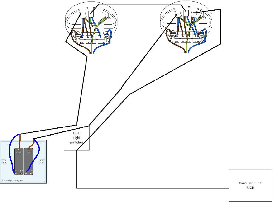
Without taking everything apart to see exactly how it's wired, it goes something like:
1. There is a long armoured cable that goes from a MCB in the house consumer unit, to the cabin.
2. This armoured cable terminates behind the wall box for the light switches. It is a dual light switch (one for inside light, one for outside).
3. There is then one cable that goes from the switch box to the outside light.
4. There is then another cable that goes from the outside light to the inside light.
5. There are then 2 cables that go between the inside light and the light switches.
Probably easier to draw than to explain:
View media item 86331
I have had a look inside the switch box and, without taking everthing apart, removing boxing on the walls, and tracing all the wires back, it's very difficult to tell what goes where specifically.
So, from the attached diagram, can someone help me to understand how this lighting circuit works? It seems overly complicated to me (I would have thought that something much simpler could have been implemented, with just a single cable going from the switch box to the inside light, and another single cable going from the switch box to the outside light).
thanks
Derek
I'm dipping into the world of home automation, and starting with a small pilot in my garden cabin/office.
One of the first things I want to do is to automate the lighting, and to do this I have a small unit that is placed inside the light switch wall box (A "Fibaro Relay Switch 2x 1.5kW), which then talks and is controlled by a computer, wirelessly. This needs to connect to both lights L/N, both switches L/N, and the mains L/N (obviously, some of these are common - see attached diagram)
View media item 86332
Before I start I want to make sure I understand how the cabin is wired today. The cabin was built about 3 years ago and the lighting wiring was installed by a professional electrician.
Without taking everything apart to see exactly how it's wired, it goes something like:
1. There is a long armoured cable that goes from a MCB in the house consumer unit, to the cabin.
2. This armoured cable terminates behind the wall box for the light switches. It is a dual light switch (one for inside light, one for outside).
3. There is then one cable that goes from the switch box to the outside light.
4. There is then another cable that goes from the outside light to the inside light.
5. There are then 2 cables that go between the inside light and the light switches.
Probably easier to draw than to explain:
View media item 86331
I have had a look inside the switch box and, without taking everthing apart, removing boxing on the walls, and tracing all the wires back, it's very difficult to tell what goes where specifically.
So, from the attached diagram, can someone help me to understand how this lighting circuit works? It seems overly complicated to me (I would have thought that something much simpler could have been implemented, with just a single cable going from the switch box to the inside light, and another single cable going from the switch box to the outside light).
thanks
Derek
")