Two Way Switch

Joined
18 Sep 2007
Messages
17
Reaction score
0
Location
Newcastle upon Tyne
Country
United Kingdom
Hello,

i'm trying to sort out the switch for the landing light. Ever since we moved in if it is on downstairs you can switch it on and off upstairs, but if it is off downstairs you can't switch it on or off upstairs. To switch it on upstairs it has to already be on downstairs. (I think that's right)

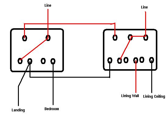
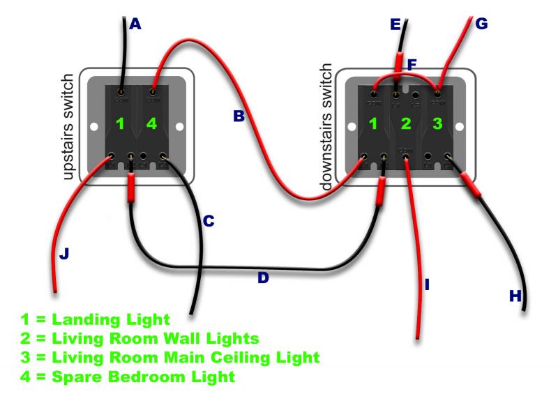
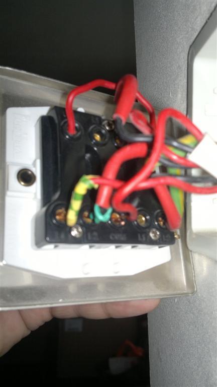
I have isolated the mains at the fuse box and individually disconnected and tested each wire in the switch with a Multimeter with an audible continuity buzzer. I used a length of wire and a connector block (to extend each wire up stairs) allowing me to touch the probes to each wire in the upstairs switch to identify each one (B,D, & E). I haven't yet taken the light fittings down to find out where the other wires (A,G,H & C) go. Finally I've got 'F' which is a short bit of cable connecting the 'COM' connections of switch 1 & 3 on the downstairs switches.

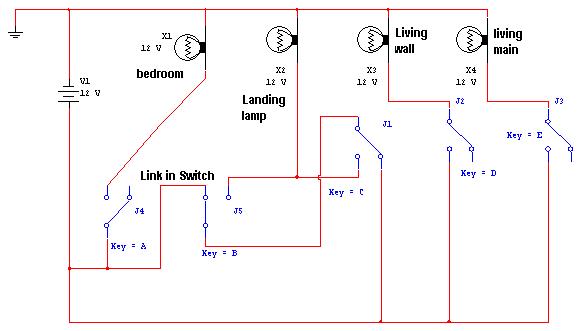
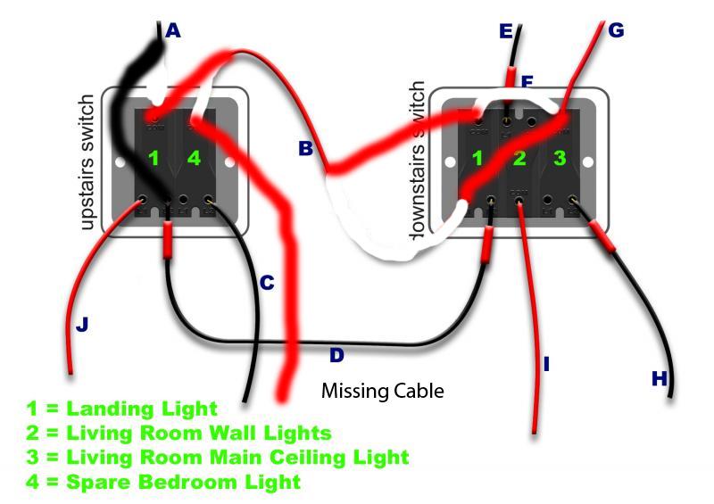
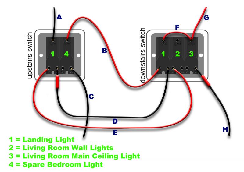
I have attached a diagram which I have created to illustrate what I've currently got. It looks nothing like the two way switch wiring diagrams I can find on the internet.


What's happening? What do I need to do to make the light work from both upstairs and downstairs?

Thanks in advance,
Mark
 
Sponsored Links
If that is truly how your lights are wired then
1. Your living room wall lights cannot work as the switch only has one conductor to that switch
2. Your spare bedroom light will only work if the downstairs landing light is on.

Where does conductor A go to.
Can we see actual pictures of the switches and wiring.
Can you advise how you have determined which wire is which. Methinks you have made some assumptions that will lead you down several garden paths.
 
Hello,

I'll recheck in the morning to be sure that my diagram is correct.

As I say in my post in order to determine which wire was which I took a 5m long wire and a multimeter.

One at a time I disconnected a wire from the switch downstairs and connected it to one end of the 5m wire with a connector block. I then took the other end upstairs and with one probe from the multimeter touching the end of the 5m wire I disconnected and checked the continuity of each wire in the upstairs switch until one beeped. I then marked it with a piece of tape. That gave me B,D, & E. I couldn't find any continuity with the other wires. My next plan was to do the same with the lights to find what wires from the switch go to what lights but it got too late to do it today.

Thanks again, Mark
 
You have 4 wires coming into switches and 4 lights this can't work there must be 5. So something must be missing.

What I would guess is either B, D, or E is in fact two wires then it will make sense.

So we have 6 wires going into the switches and two wires between the switches.


This is likely how they are wired. Only way they can work with just 6 wires. So line would loop to three switches on one bank and two switches on other bank so 2 line wires and 4 lamp wires with two wires between the switches.

Either that or you have count wrong.

The odd wiring is because done with Multisim which allows me to test it all. Ignore the earth software will not run without it but it should not really be there.
 
Sponsored Links
To give some idea here is a standard wiring diagram
lights.bmp

Took more care with this one to draw circles around the wires forming a cable. X2 is the two way lamp and between the two switches it shows three wires. In your case there are only two wires and the bottom of the two switches gets its line supply from another switch in the group.

This method has been discontinued there are two problems.
1) It can produce mains hum on radios, TVs etc. as feed and return don't take same route.

2) Where the upstairs and downstairs lights run from a different fuse or MCB it can result in a borrowed neutral situation and with RCD protection it can trip the RCD plus is dangerous.

However with same fuse or MCB it does work and there is no regulation I can find which bans it. Just bad practice.

Good luck
 
Looks like A is landing switch wire.

DE are strappers, but should connect to L1 and L2 of the landing switch on the downstairs plate. At the moment they are straddling two switches.

The rest, as has been mentioned, does not quite add up, unless some of your lights are inoperative.
 
Hello again Chaps,

Right as you all correctly spotted I made a balls up with my diagram. I had the middle switch upside-down and one of the wires I thought had continuity doesn't. Not sure how I managed that but I have now checked, rechecked and checked again to be sure.

The following diagram is I am sure what I have at the moment.


So wires E and I make sense, they are the Living room uplighters.

It's probably worth mentioning that the spare bedroom light is on the upstairs fuse where as the landing light is on the downstairs fuse. (I am knocking the lot off when working on them).

I have also discovered by playing with different switch configurations that the way the main light in the living room is switched effects the landing light.

I have taken a couple of photos although they are not very clear. The bits of insulation tape are simply there to identify each wire I'll remove them when I've done.

 
It's still nonsense.

Switches 2,3 & 4 should have a permanent live at one end and switched live to a light at the other.

Switch 1 should have permanent live to one single end at one switch and switched live to a light at the single end at the other.
The two terminals at the double end of both no 1 switches should be connected by two wires.

All the permanent live connections can be links from one supply wire.
 
First step -

Remove the link between switches 1 & 3.

Do the living room wall and main lights work as they should?
 
First the down stairs switch.

The line link should go to L1 or L2 not Com so that's wrong.

Upstairs complete mess up as down stairs link should go to two way switch only. There seems to be a wire missing. Most cables come with red and black so should be same number of reds and blacks. You show one more black wires than red wires.

I will guess wire C has a red wire unused in the cable which should replace wire B in the diagram then the bedroom light would work with no connection to downstairs? Assuming this works then. B at top switch is now not being used so.

Now I can only guess as I can't test any wire but I would start (with power off of course) by swapping the link with B at bottom switch.

Now replace A with B at top switch.

Now put A in with D at the top switch.

I think that should work. Please did I get it right?

As a PS if the down stairs lights affect landing then likely link taken from wrong side of switch 3
 
I disagree.

All it would need to make the diagram 'look' alright would be to swap the two red wires at the landing switch.

However, without testing, no one can be certain.
 
This is what I am guessing should be there. But as you say we can only guess we have no readings to go on.

Other than considering there is a line wire tucked away somewhere nearly the same diagram as I posted last night before he realised his mistakes.
 
I agree with EFLI that swapping the reds would make it look, on paper, OK.

But, as the amended diagram stands, the spare room light would not work unless the downstairs landing light switch is in a certain position.
 
Although we can guess that G is line feed and H is to light it is only a guess.

The same applies A, J, and C three wires and really only guessing where they go.

There are some things we do know. Neither bedroom or Landing will work correct as shown.

With two wires between switches one must go into Com and will be on it's own and the other will go with another wire in the same hole with the switch connected to light.

But until we have a list with for example:-
A = Supply to landing lamp
B = Com Strap Cable
C = Feed to Bedroom light
D = L1 Strap Cable
E = Wall lights feed
F = Live link
G = Feed from ceiling lamp
H = Feed to ceiling lamp
I = Feed from Wall lamp
J = Feed from landing lamp
X = Missing wire feed from bedroom

Then we are guessing

I must say it was very good diagram even if it was wrong. Even the shadows on the cables.
 

DIYnot Local

Staff member

If you need to find a tradesperson to get your job done, please try our local search below, or if you are doing it yourself you can find suppliers local to you.

Select the supplier or trade you require, enter your location to begin your search.


Are you a trade or supplier? You can create your listing free at DIYnot Local

 
Sponsored Links
Back
Top