Ultracom 30CXI - Want to remove time clock

Joined
8 Jan 2021
Messages
9
Reaction score
0
Country
United Kingdom
Hi everyone

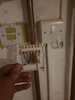
I have inherited a Glowworm Ultracom 2 CXI. It has a receiver for a Salus Thermostat wired into it AND a time clock on the front. The Salus wireless thermostat has never worked. No matter what we tried the boiler would never get a signal to turn the heating on. We tried setting the time clock to permanently on but the Salus thermostat did not override it. So instead we just used the time clock on timer.

I want to install a Nest stat but need to know how to disable the time clock so that the Nest will actually work.

Can anyone help me please this has been bugging me for ages.

I have uploaded a few photos.

Thanks in advance

20210108_190036.jpg 20210108_185929.jpg 20210108_185904.jpg 20210108_185853.jpg
 
Sponsored Links
You want the single channel version of Hive.

images


And the wires simply move from the Salus receiver to the terminals at the Hive receiver that have exactly the same function. From your photo it looks like a Salus RT500RF So:

Salus N = Hive N
Salus L = Hive L
Salus Com = Hive Common (1)
Salus NO = Hive NO (3)

You will have to leave the boiler timer set to be 'on' 24/7, and then the Hive will take total control.
 
Hi Stem

Thanks for this.

So how come when I have set the time clock to permanently on, the Salus has never took full control?

Also, o was hoping to install a Nest instead of Hive. Is the wiring similar to the Hive diagram above?
 
Normally there is a timer that sets the time that the heating is required to be 'on' this is wired in series with a thermostat that controls the temperature, but only when the timer tells it to operate. This is what you have now.

The Nest (Sorry my bad about the Hive :whistle:) is a different beast, it has both time and temperature control in the one device. So the existing timer should never switch the Nest (or Hive) off. Therefore it should be permanently on.

For Nest it depends on which version you wish to install. For the Nest-e:

Salus Com = Nest Com
Salus NO = Nest NO

Nest-e is battery operated so the N and L are not required and should be isolated safely.

On the other hand, if it's Nest 3rd Gen

Then:

Salus N = Nest (N)
Salus L = Nest (L)
Salus Com = Nest Heating - common (2)
Salus NO = Nest Heating - call for heat (3)
 
Sponsored Links
You want the single channel version of Hive.

images


And the wires simply move from the Salus receiver to the terminals at the Hive receiver that have exactly the same function. From your photo it looks like a Salus RT500RF So:

Salus N = Hive N
Salus L = Hive L
Salus Com = Hive Common (1)
Salus NO = Hive NO (3)
He says they want a Nest not a Hive
You will have to leave the boiler timer set to be 'on' 24/7, and then the Hive will take total control.
 
Be carefull what you are doing , looking at your pics of the boiler end , there are no wires in the 230V thermostat switching terminals, so looks like the boiler is wired 24V switching, DO NOT make any links or you will damage the boiler
 
Be carefull what you are doing , looking at your pics of the boiler end , there are no wires in the 230V thermostat switching terminals, so looks like the boiler is wired 24V switching, DO NOT make any links or you will damage the boiler

I do not want to touch the boiler wirings itself. I turned the boiler off at the fused spur and took them photos to see if anyone could spread some light on why it hasn't worked previously.

I am happy to change the thermostat receiver though. But I did not intend on touching the wiring in the boiler.

Should I be concerned though about how the boiler has been wired up?
No it is perfectly normal to wire up using 24v terminal, I meant do not put any links in your nest wiring, many posts on here will show links being used, dont copy them , yours is not wired the same as those
 
If you are just swapping the existing Salus receiver for a Nest receiver, like for like, exactly as it is now, it won't be a problem.
 
The Salus wireless thermostat has never worked. No matter what we tried the boiler would never get a signal to turn the heating on. We tried setting the time clock to permanently on but the Salus thermostat did not override it. So instead we just used the time clock on timer.

Reading that again, If I understand it correctly, only the boiler timeswitch turns the boiler on and off. The Salus does nothing. If that is correct, the Salus receiver will actually be permanently 'on' [As the two devices are wired in series, the timer and the Salus would both need to be 'on' at the same time for the heating to operate]

However, it is unusual for a Salus receiver to fail in the 'on' position, normally they fail in the 'off' position. Therefore I suspect that if it has failed in the 'off' position someone may have bridged the Salus wiring to get the heating to work.

In the back of the receiver, as well as the N & L mains supply, I would expect to see one wire in the 'COM' terminal and one wire in the 'NO' terminal. If yours is different, say for example there is a link inserted between the COM and NO, terminals, or that there are two wires in one of the terminals and nothing in the other that is what has happened.

If you do find anything unusual, and you need further assistance, post a photo of the wiring connections at the back of the Salus receiver.
 
So having bought a standalone Hive, I have wired the reciever up as was told above, it's all working, as in the thermostat is sending a signal to the reciever correctly, but my boiler completely ignores it just like it did on the previous thermostat.

I have attached the wiring photo for the Hive receiver.

I have tried the boilers time clock on permanent on and permanent off and neither setting allows the hive to take control.

Any ideas?
 

Attachments

  • 20210111_181913.jpg
    20210111_181913.jpg
    161.5 KB · Views: 126
Those connections for swapping a 4 wire connection from Salus to a Hive single channel version look good to me.

However to assist further, we would need to know what each of the 4 wires are physically connected to at the other end. The L & N would appear correct if the receiver is working, but what are the black and grey wires connected to?

I have seen installations where the thermostat was left over from an old installation and not actually connected to a new boiler at all, or a faulty thermostat has had its wiring altered to bridge it out of circuit and keep the heating on. From what you describe the second would seem more of a possibility in your case.

Just a note of caution. If you have to open up a sealed part of the boiler to access the wiring terminals to check, this is not a DIY job. It should be done by a Registered Gas Installer (RGI) who can carry out the necessary safety checks afterwards. However, looking at your photos it would appear not to be the case to me, but my skills are electrical, not gas related.
 
Last edited:
Hi Stem

I actually put a photo up on my original post of where the wires went in on the boiler. I will re-attatcg the photo now.
 

Attachments

  • Screenshot_20210111-194714_Chrome.jpg
    Screenshot_20210111-194714_Chrome.jpg
    100.6 KB · Views: 118
yes that is the 24v switching,no problem with it being wired in there
 

DIYnot Local

Staff member

If you need to find a tradesperson to get your job done, please try our local search below, or if you are doing it yourself you can find suppliers local to you.

Select the supplier or trade you require, enter your location to begin your search.


Are you a trade or supplier? You can create your listing free at DIYnot Local

 
Sponsored Links
Back
Top