Vent sucking in air

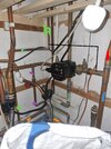
This might be better , blue is from boiler, red is vent, green is feed from tank, purple is bypass and orange is return to boilerView attachment 292854

I would reposition the cold feed to between vent and pump. Personally I'm not keen on the vent going straight up from a tee like that, as it's more likely to cause flow out of the vent (the opposite problem to what you have now). I prefer the vent to come off the top of a horizontal run. Might be a bit tight, but hopefully it will go in. The cold feed should go up and under into the pipe, to reduce convection warming the header tank, and encouraging algae growth.
 
Last edited:
Sponsored Links
This should solve it, VCP system, from the boiler, Vent, Coldfeed, Pump.
Balank off the cold feed where it joins the boiler return
 

Attachments

  • VCPdd rev1.jpg
    VCPdd rev1.jpg
    365.7 KB · Views: 47
Who fitted the pump? Whoever did that should have run and tested the system properly, this could all have been easily rectified at the time.

th


Your looking to implement pic 3. As suggested above - it would flow from the left to the right - flow from the boiler, the vent, the feed then the pump. Minimise the distance between the feed and the vent, ideally within 150mm of each other.
Be helpful to show the boiler location on those sketches.
And cold feed should be up and under (à la Eddie Waring, if you remember him).
 
Sponsored Links
There are lots of systems with the pump on the boiler return and the installation is like this. Most have the upstairs rads and the cylinder coil teed off this rising vent, I have also seen some with the cold feed teed into the cylinder return, at the cylinder bottom, cylinder located upstairs.

In the schematic below, why is there a negative pressure at the pump suction with the cold feed tied in practically at the pump inlet, I would have thought that the pressure there would be the static head, say 4.5M with boiler located at ground level anf if the pump head is say 3.5M then the pressure at the pump discharge would be 8M. If the cold feed was at the pump discharge then would expect the pressure at the pump discharge to be 4.5M and 1.0M at the pump suction.


1674062265723.png
 
Last edited:
In the schematic below, why is there a negative pressure at the pump suction with the cold feed tied in practically at the pump inlet,
There isn't. As you say, the pressure at that point is 4.5m. On the configuration shown, using pump suction level as the datum, the pressure at pump discharge is 8m. Assuming (say) 2m loss across the boiler and a bit of pipe, the pressure at the vent connection is 8 - 2 = 6m. That's 1.5m above the water level in the header tank so would cause flow from the vent.
Better to put the open vent on the pump suction upstream of the cold feed, with the downside of not having the vent directly after the boiler, or put the cold feed on the boiler flow, after the open vent, with the downside that the pressure at pump suction is lower, static head 4.5m minus rad friction loss 1.5m assumed = 3m. Pros and cons, but either would be OK in practice IMO.
Some advantage with pump on boiler return - lower temperature at the pump, and higher boiler pressure meaning less chance of air ingress, but I believe pump on the flow is more common, though somebody might correct me on that.
 
Last edited:
Is that a shower pump with the flexible pipe?
Was this installed and then the problems began?
It looks like a newer addition.
Is this is what is pumping faster than it can be fed and so sucking in air
 
There isn't. As you say, the pressure at that point is 4.5m. On the configuration shown, using pump suction level as the datum, the pressure at pump discharge is 8m. Assuming (say) 2m loss across the boiler and a bit of pipe, the pressure at the vent connection is 8 - 2 = 6m. That's 1.5m above the water level in the header tank so would cause flow from the vent.
Better to put the open vent on the pump suction upstream of the cold feed, with the downside of not having the vent directly after the boiler, or put the cold feed on the boiler flow, after the open vent, with the downside that the pressure at pump suction is lower, static head 4.5m minus rad friction loss 1.5m assumed = 3m. Pros and cons, but either would be OK in practice IMO.
Some advantage with pump on boiler return - lower temperature at the pimp, and higher boiler pressure meaning less chance of air ingress, but I believe pump on the flow is more common, though somebody might correct me on that.
add shower pump data then recalculate
 
Is that a shower pump with the flexible pipe?
Was this installed and then the problems began?
It looks like a newer addition.
Is this is what is pumping faster than it can be fed and so sucking in air
Looks like a shower pump with flexis in the photo, but that will be on the 2ndary circuit, so unrelated to the problem.
 

DIYnot Local

Staff member

If you need to find a tradesperson to get your job done, please try our local search below, or if you are doing it yourself you can find suppliers local to you.

Select the supplier or trade you require, enter your location to begin your search.


Are you a trade or supplier? You can create your listing free at DIYnot Local

 
Sponsored Links
Back
Top