I know our local substation has 11kv coming in and the first 3 houses all have different phases, but all the neutrals go back to the star point in the substation which is then earthed to the ground. Surely our neutral at the star point don't actually touch the other 3 phases does it?

You are using an out of date browser. It may not display this or other websites correctly.
You should upgrade or use an alternative browser.
You should upgrade or use an alternative browser.
What exactly is the star point?
- Thread starter DIYedboy
- Start date
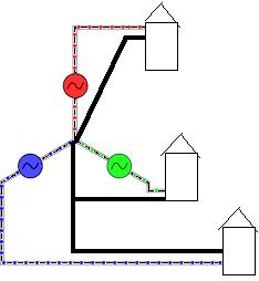
our side of the transformer is made of 3 big coils of wire ( for ease of description ) ..
on the one end of each coil is the wire bringing the live to your houses.. ( one for each phase.. )
the other ends of the coils are connected to each other and then to a big hunk of metal burried in the ground..
this is the star point and is where the neutral comes from..
on the one end of each coil is the wire bringing the live to your houses.. ( one for each phase.. )
the other ends of the coils are connected to each other and then to a big hunk of metal burried in the ground..
this is the star point and is where the neutral comes from..
The star point is common to all 3 phases yes. It is at the centre of all 3 phases, each phase being 120 apart from the next.
There is a bit of a piccy at the bottom of this article which shows a 3 phase star system: http://www.ukslc.org/articles/power/3_phase_power_explanation.html
There is a bit of a piccy at the bottom of this article which shows a 3 phase star system: http://www.ukslc.org/articles/power/3_phase_power_explanation.html
The neutral at the star point is also connected to earth. So it is at the zero volts point of each phase, whereas the line connection is at 230v nominally.
There is a diagram of this at http://www.tlc-direct.co.uk/Book/5.1.1.htm
There is a diagram of this at http://www.tlc-direct.co.uk/Book/5.1.1.htm
points for the best reply?
- Joined
- 27 Jan 2008
- Messages
- 29,116
- Reaction score
- 3,567
- Location
- Llanfair Caereinion, Nr Welshpool
- Country

Each house is feed with one phase only which gives 230V this is at least how it is done in the UK for most houses. Out lying farm houses etc. may only have a single phase supplied.
In other countries there are some odd systems the USA have many including the "Hot Wire" system so be careful to select UK web pages.
As to why we use three phase this is so in industry it can run large motors with ease. Problem is once generated as 3 Phase the 3 Phases need to be balanced so by using three phase transformers in a housing estate it helps keep the whole system balanced. It also means the neutral wire carries less current and but fitting multiple earth rods or using the outer casing as earth it means it is both cheaper and in the main safer although with the new regulations asking for RCD protection on most circuits the main advantages of the combined earth and neutral are not longer being taken advantage of and maybe in the future thinking will change on use of PME supplies.
Because of the three phase system if a fuse blows in the main transformer you could loose your supply but you neighbours may still have a supply. Looking up the street you could see every third house with power failure.
Cost of course also plays a part when one 4 core cable can carry three times the power of a two core cable.

Brilliant, thanks lads thanks for all your help..........Taylor2 that TLC diagram really helped me (could never get me head round that star diagram), so all 3 house neutrals get connected to each other, their own transformer windings and to earth back at the substation.So, if house A is using 50 amps, house B 20 amps and house C 5amps, is all that current returning up their neutrals going to earth? or is it going back through the windings and down to it's house again?
houses A, B and C all have exactly the same current going down their own neutral as up their own line. They all share the same neutral.
You might have thought that the neutral would add up the currents for the 3 houses.
However, the neutral for all the phases cancel each other out, so there is less current going back to the star point.
If all the houses used exactly the same current, their neutals would cancel each other out completely. However as they will not be exactly in balance, there will be something.
If you had 3-phase equipment its phases should be in balance so the neutral would carry no current.
- Joined
- 27 Jan 2008
- Messages
- 29,116
- Reaction score
- 3,567
- Location
- Llanfair Caereinion, Nr Welshpool
- Country
There is a quick way which is not exact but very close;
Example;
L1 = 50A
L2 = 20A
L3 = 5A
Subtract the smallest current from the other two:
L1 - L3
L2 - L3
50A - 5A = 45A
20A - 5A = 15A
The square root of (45(squared) - 15(squared)) = 42.42641A
So current on neutral = 42.42641A
The other way is a phasor diagram and nodal analysis. Which unless you are very good with maths will probably be over you head and I would need to get my books out the refresh how to do it.
I understand the 3 phase system but am alittle confused with star-delta transformers. Are these actually 3 transformers with independant cores? All drawings show a common core but surely the magnetism would cancel if all three phases were present.
Nice one Ericmark, but that reduced current that is left because the phases aren't balanced,what happens to that? Is it flowing to earth? does it just disappear? or does it flow back into the windings and pick up more voltage and get shot back down the phase toward the house again?
- Joined
- 27 Jan 2008
- Messages
- 29,116
- Reaction score
- 3,567
- Location
- Llanfair Caereinion, Nr Welshpool
- Country
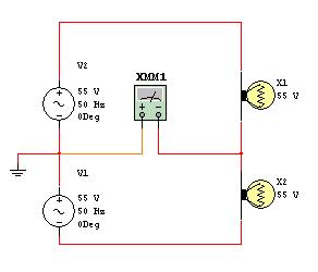
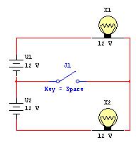
For a moment think of the two phases or split phase as it's called used on 110v systems in UK building sites etc.
Here I have connected ammeter to where the earth should be and shown two bulbs in series. If the centre tap earth was removed it would make no difference to the two bulbs working.
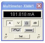
If the bulbs were different sizes then current would start to flow. For example if top one was 20W and bottom 10W then the ammeter would show 182ma. I am sure I do not need to show ammeter twice with 0 reading as well!
Same idea with three phase but 3 instead of 2 wires.
Sorry missed star / delta question.
This is rough showing of a star / delta transformer 6 coils of wire around the green laminated core. The power in goes into the bottom windings shown in delta and power out in star shown with top winding.
You can of course have power out delta too this is called the IT system and is used on some odd places abroad I found in on a tunnel boring machine and in the USA some areas have what the call the "Hot Wire" system. But in the UK all secondaries on supply transformers will be wired star.
If the bulbs were different sizes then current would start to flow. For example if top one was 20W and bottom 10W then the ammeter would show 182ma. I am sure I do not need to show ammeter twice with 0 reading as well!
Same idea with three phase but 3 instead of 2 wires.
Sorry missed star / delta question.
This is rough showing of a star / delta transformer 6 coils of wire around the green laminated core. The power in goes into the bottom windings shown in delta and power out in star shown with top winding.
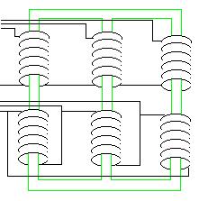
You can of course have power out delta too this is called the IT system and is used on some odd places abroad I found in on a tunnel boring machine and in the USA some areas have what the call the "Hot Wire" system. But in the UK all secondaries on supply transformers will be wired star.
Thanks for the drawing Ericmark, i've spent a few days lookin at it, but I'm embarrassed to say, I still can't get it, surely that wire and ammeter make a short circuit to earth because the voltage path through that is easier than through the second lamp?
- Joined
- 27 Jan 2008
- Messages
- 29,116
- Reaction score
- 3,567
- Location
- Llanfair Caereinion, Nr Welshpool
- Country
lets look at DC then can you see that in the drawing the switch will make no change to how the lights work? As long as the bulbs are the same size. However if you put different wattage bulbs in so they do not match each other then unless you close the switch you will not get same voltage on both lamps.
The neutral is where the switch is shown.
The neutral is where the switch is shown.
Electricity (with a few exceptions that we don't need to go into here) flows in complete loops.Nice one Ericmark, but that reduced current that is left because the phases aren't balanced,what happens to that? Is it flowing to earth? does it just disappear? or does it flow back into the windings and pick up more voltage and get shot back down the phase toward the house again?
Consider the single phase case, your electricty flows in a loop through the transformer, the wiring and your load. Since it's AC the direction of flow in this loop reverses 100 times a second.
The three phase with neutral case is pretty similar, you have 3 loops but they share a section and because different loops are flowing in different directions the current in the neutral is partially canceled.
DIYnot Local
Staff member
If you need to find a tradesperson to get your job done, please try our local search below, or if you are doing it yourself you can find suppliers local to you.
Select the supplier or trade you require, enter your location to begin your search.
Please select a service and enter a location to continue...
Are you a trade or supplier? You can create your listing free at DIYnot Local
Similar threads
- Replies
- 8
- Views
- 4K