Why we pay professional, qualified, registered sparkies

Joined
4 Nov 2010
Messages
6,139
Reaction score
656
Location
Cumbria
Country
United Kingdom
Apologies to those of you at whom this really isn't aimed.

Finished wiring up extra sockets in my mates kitchen at the weekend (of course, neither planned nor started before April ;)). Before fitting the last one, did continuity tests round the ring ...

rn - 0R29
r1 - 0R60

Hmm, that's not right. But where to start looking ?
So I thought, lets look at the one connection I've not been into - the ring ends in the CU. And lo, find one of the live ends isn't firmly fastened in the breaker - it pulled out by hand. So popped the ends out and refitted them. But while it'm tugging to get that extra mm of cable*, see the live of the cooker circuit lift out of it's terminal :eek: I'll add that the cooker circuit had acceptable R1+R2 when I checked it a couple of weeks ago.

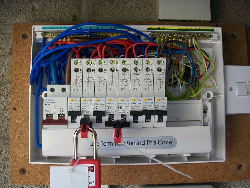
* It was a CU replacement a year or so ago, and some of the tails weren't "generous" in length. Paid a professional sparky to fit it as cheaper than LABC fees.

Of course, the CU is so neatly done that it's a joy to work in :rolleyes:
 
Sponsored Links
Hi Mate

To be honest, thats just personal pride and standards in what you do that makes that look a mess. I wouldnt leave it like that nor would i leave a terminal hanging by a thread and im not qualified or registered.
Anyway, im working towards the latter 2 as we speak so in my ever expanding knowledge on domestic electrics. what do Rm and R1 mean? I know the resistance bit. Also ive never seen a ohms value written like 0R29 what does that mean?
Sorry for the questions Simon but like i said, im eager to learn as much as i can.

Thanks
 
I have found where terminals have been tightened with a torque driver the wires are still lose. The problem with any screw terminal is one strand of wire can bind the screw so although it feels tight and the wires also feel firm after a month of natural vibration it is found that in fact it was not the case.

The screw terminal is not maintenance free and in industry we have routine maintenance which includes testing screw terminals. In fact it has caused problem due to the maintenance where continual tightening of screws has caused the cable to be severed.

The problem with domestic is the client is normal very price orientated and for an electrician to charge for returning to re-test his work would in the main mean he got no work because he was over priced.

The fact they now have to make out paperwork does mean in the future one can look at the paperwork and simply compare readings to show if there is any change so more easy to be alerted to any problems arising.

So question is did the paperwork raised by the electrician match the readings you have taken? If he also had readings which should have rang alarm bells then clearly he was in the wrong. But if not then although we may suspect he was shoddy we have really to give him benefit of the doubt.
 
Sponsored Links
Hi Mate

To be honest, thats just personal pride and standards in what you do that makes that look a mess. I wouldnt leave it like that nor would i leave a terminal hanging by a thread and im not qualified or registered.
Anyway, im working towards the latter 2 as we speak so in my ever expanding knowledge on domestic electrics. what do Rm and R1 mean? I know the resistance bit. Also ive never seen a ohms value written like 0R29 what does that mean?
Sorry for the questions Simon but like i said, im eager to learn as much as i can.

Thanks
By replacing the decimal point with the R it means the point is not missed but since all readings will be using a decimal point we as installation electricians would not bother doing it that way. That's the way an electronic engineer would write it.

The R1 and R2 values are the names given to the loop resistance and the standard installation forms will have (R1 + R2) column 6 and R2 column 7 and if R2 is recorded the (R1 + R2) is not required.

With a ring we can measure the earth ring resistance so will enter R2 but with a radial it would require a long cable to measure just the earth resistance so we measure the earth and the live resistance. Once powered up we have a meter able to measure directly the Line to earth impedance (with AC resistance is called impedance) and we before the introduction of RCD's would use these readings to ensure the automatic disconnection device would disconnect the supply should there be a fault.

Today the earth loop impedance can be very high and still trip the RCD but the line - neutral impedance can be used to calculate volt drop.
 
A lot of your issues have to do with that dreadful CU.

A decent brand such as hager has enough room inside to make a tidy job of the installation, and I would imagine better terminals in the OCPDs.
 
Also ive never seen a ohms value written like 0R29 what does that mean?
In 'modern parlance' (I was brought up on resistors in the 60s!), 'R', 'K' and 'M' are used to indicate the position of the decimal point and the multiplier. hence, as illustrative examples:
0R29 means 0.29Ω
1R (or 1R0) means 1Ω
4R7 means 4.7Ω
2K2 means 2.2kΩ
56K means 56kΩ
3M3 means 3.3MΩ
etc.

Kind Regards, John
 
  • Thanks
Reactions: SNM
A lot of your issues have to do with that dreadful CU.
Yes, they are a bit short of space. But it can be done better if the person doing it actually tries.
A decent brand such as hager has enough room inside to make a tidy job of the installation, and I would imagine better terminals in the OCPDs.
Terminals seem similar to other makes I've worked with. But then any decent brand would have been at least 3 times the price and ruled out RCBOs on price :(


So question is did the paperwork raised by the electrician match the readings you have taken? If he also had readings which should have rang alarm bells then clearly he was in the wrong. But if not then although we may suspect he was shoddy we have really to give him benefit of the doubt.
Of course, he did r1 and r2 tests before putting the ring tails into the breaker - so it wouldn't have shown up at the time. Ultimately, measuring the ring conductivity means that at least one set of connections are done after taking the measurements.
 
I was taught that method of writing resistance at college, but it doesn't seem to be that often used in the electrical world. I think it's more of an electronics industry standard.

I was also taught the resistor colour code, which I still remember.
 
The R1 and R2 values are the names given to the loop resistance ...
To perhaps be a little clearer, R1 refers to the resistance of the line/live/phase conductor, and R2 to the resistance of the CPC ('earth') conductor (and Rn to the resistance of the neutral conductor). As eric implies, in the event of a live-CPC fault (short), part of the 'fault loop resistance/impedance' through which the resulting fault current flows will be determined by (R1+R2). In the case of an L-N fault (short), the 'fault loop resistance/impedance' of relevance will be (R1+Rn).

This terminology seems very well-established and accepted in terms of electrical installations, although, having much 'wider' fileds of interest, I personally don't think I would ever have chosen things as ubiquitous (and not self-explanatory) as 'R1' and 'R2' for this purpose - why not RL and RC, for example?!

Kind Regards, John
 
I was taught that method of writing resistance at college, but it doesn't seem to be that often used in the electrical world. I think it's more of an electronics industry standard.
Yes, it's more of an electronics thing. However, as eric pointed out, there's a lot to be said for it, since one is far less likely to 'miss' an R, K or M tha one is likely to miss a decimal point - e.g. one could misread 4.7k as being 47K, but would not make that mistake if it were written 4K7.
I was also taught the resistor colour code, which I still remember.
Weren't we all! ... although I started using the colour code before the days of stripes (i.e. in the 'body, tip, dot' era!). Most small resistors are still colour-coded (with stripes), so you'd still need to know the code today if you were dealing with resistors.

Kind Regards, John
 
I have questioned what is entered onto an installation certificate in the past. To me to measure R2 is all well and good with a ring but in service the loop tester measures R1 + R2 and what we want is to be able to highlight any degrade in the system quickly and easy so where only R2 is recorded to compare one has to isolate the supply and test with a low ohm meter.

I also question lack of line - neutral impedance at the furthest or most central socket so it can be compared with the line - neutral at the CU to calculate volt drop.

Over time circuits get altered and it becomes impossible to lay blame at any ones door as we don't have a clue what was there to start with.

My mother has just had a supply connected by social services to her door bell so she does not have a problem with discharged batteries. Simple job use existing wiring but change a 8 Vac transformer for a 12 VDC power supply. I asked electrician about a minor works and he rightly said that since simply changing a power supply not really required. However he could not get a 12Vdc power supply to directly replace the existing and instead had to fit a socket and used a power supply which plugged into a socket. To my mind he should have provided us with a minor works as a new socket had been fitted but no paper work was left.

As with the guy who started the post I will when I get time take my test set and test it myself. But as to what to do if it should fail well that's another story. Likely I will find it is not RCD protected and it does not have a label on it to say for door bell use only.

So should I make a fuss or should I just print a label saying for use with door bell only?

Same with posters problem. Is it really worth making a fuss? He has what he wanted a bit of paper.
 
Yes, it's more of an electronics thing. However, as eric pointed out, there's a lot to be said for it, since one is far less likely to 'miss' an R, K or M tha one is likely to miss a decimal point - e.g. one could misread 4.7k as being 47K, but would not make that mistake if it were written 4K7.
When I was taught to do it that way it was explained that it was not so much people mistakenly missing the DP, more that it could actually go missing when drawings and schedules were duplicated/copied and the quality deteriorated.
 
Betty Brown Runs Over Your Garden But Violet Grey Walks

Hey I still remember it 50 years on. Maybe I'm not losing my marbles after all.


Is it time for my walk?
 
I have questioned what is entered onto an installation certificate in the past. To me to measure R2 is all well and good with a ring but in service the loop tester measures R1 + R2 and what we want is to be able to highlight any degrade in the system quickly and easy so where only R2 is recorded to compare one has to isolate the supply and test with a low ohm meter.
You are probably right but you can calculate from R2 what R1 and Rn should be and compare it to the loop value.

I also question lack of line - neutral impedance at the furthest or most central socket so it can be compared with the line - neutral at the CU to calculate volt drop.
As PSCC will be higher than or the same as the PEFC it is not necessary to record it.
Recording it would show that it was done and so would a tick.
Rarely in a usual sized properties is volt-drop a problem but, if likely, this will also be indicated by the loop value.

To my mind he should have provided us with a minor works as a new socket had been fitted but no paper work was left.
He should.

So should I make a fuss or should I just print a label saying for use with door bell only?
Same with posters problem. Is it really worth making a fuss? He has what he wanted a bit of paper.
I would as it is Social Services.


Edited error with PSCC
 

DIYnot Local

Staff member

If you need to find a tradesperson to get your job done, please try our local search below, or if you are doing it yourself you can find suppliers local to you.

Select the supplier or trade you require, enter your location to begin your search.


Are you a trade or supplier? You can create your listing free at DIYnot Local

 
Sponsored Links
Back
Top