Wiring of Salus RT510RF thermostat to Vaillant combi

Joined
21 Nov 2017
Messages
4
Reaction score
0
Country
United Kingdom
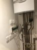
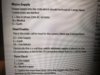
How do I wire a Salus RT510RF thermostat receiver to Vaillant Ecotech Plus 837 combi boiler? Live and Neutral are fairly obvious but what about the COM and NO from the Salus to which connector on boiler circuit board?
Thank you for any help.
Vaillant pc board.jpg
 
Sponsored Links
See the little red wire loop in the terminals 24v RT (Room Thermostat) remove that, and wire the two terminals where it came from to COM and NO, it doesn't matter which way around they go. As you will see, these wires are 24v so do not connect them to anywhere else other than COM and NO which are voltage free contacts.
 
So should be like diagram attached? I understand that the Salus can be volt free or 240v. I appreciate your answer and will probably use the 24V as you explained but out of interest could the lilac 240v RT connection be used?
Thank you Stem
 

Attachments

  • wiring diagram.pdf
    452 KB · Views: 2,496
First of all, yes your drawing is correct.

And yes, you could use the 230V RT terminal, but it is slightly more complicated and involves the use of a link wire at the Salus, so I proposed what I considered to be the most straightforward & easiest method.

Also, the mains method only requires 3 wires to be run between the Salus and the boiler, instead of 4. Often then there is a temptation to use standard 3 core cable and use the earth wire as the third connection which is not good practice.

I always run two separate cables, one for the 24v and a separate one for the 230V, supply. Combining 230V and 24v in the same cable is also not good practice.
 
Sponsored Links
Thank you for your prompt reply and help.
I will wire using the 24v connection and use separate cables as you suggest. Best to keep to good practice.
 
Thank you Stem. Just to say that I installed Salus over weekend using 24v and two separate cables as you advised. All working fine so far and long may it continue!
 
First of all, yes your drawing is correct.

And yes, you could use the 230V RT terminal, but it is slightly more complicated and involves the use of a link wire at the Salus, so I proposed what I considered to be the most straightforward & easiest method.

Also, the mains method only requires 3 wires to be run between the Salus and the boiler, instead of 4. Often then there is a temptation to use standard 3 core cable and use the earth wire as the third connection which is not good practice.

I always run two separate cables, one for the 24v and a separate one for the 230V, supply. Combining 230V and 24v in the same cable is also not good practice.


Stem, I need to wire the boiler into a wiring centre and it wants it to be done 'volt free'. Can you please advise? Which ports on the boiler should i use? I have the same boiler as pictured above
 
If it's the same boiler you do it exactly the same. It is the thermostat switch contacts that are described as 'volt free' which means that aren't connected to the 230V supply and they will switch any voltage that is applied to them. So they can be used with 230V or 24v. In the case of the example above it's 24v.

It's unusual though to have a wiring centre with a combi boiler though. Is that what you mean?

wc.jpg


They are normally associated with systems that have a hot water cylinder or several heating zones and are fitted with motorised valves. If that is the case the installation is completely different, the thermostat controls the motorised valves and not the boiler directly.
 
If it's the same boiler you do it exactly the same. It is the thermostat switch contacts that are described as 'volt free' which means that aren't connected to the 230V supply and they will switch any voltage that is applied to them. So they can be used with 230V or 24v. In the case of the example above it's 24v.

It's unusual though to have a wiring centre with a combi boiler though. Is that what you mean?

View attachment 176966

They are normally associated with systems that have a hot water cylinder or several heating zones and are fitted with motorised valves. If that is the case the installation is completely different, the thermostat controls the motorised valves and not the boiler directly.

So I can wire into the 230V RT (Pinky terminal next to the mains power).

I have an under floor heating system and a separate radiator zone upstairs. I’m using the Heatmiser under floor heating 8 zone wiring centre
 
So I can wire into the 230V RT (Pinky terminal next to the mains power).

I have an under floor heating system and a separate radiator zone upstairs. I’m using the Heatmiser under floor heating 8 zone wiring centre
 

Attachments

  • F25D97D3-90F7-41A8-98A8-43D6E1583AF0.jpeg
    F25D97D3-90F7-41A8-98A8-43D6E1583AF0.jpeg
    180.7 KB · Views: 780
  • 447CB750-D437-4C5E-A58E-B77A56922D1B.jpeg
    447CB750-D437-4C5E-A58E-B77A56922D1B.jpeg
    143.3 KB · Views: 4,385
  • 1F5E4D4A-B0D0-4BD4-85FA-A58F20AFFA73.jpeg
    1F5E4D4A-B0D0-4BD4-85FA-A58F20AFFA73.jpeg
    559.9 KB · Views: 466
Sorry I have no experience of a 'Heatmiser under floor heating 8 zone wiring centre' so can't give specific advice on that I'm afraid.

However, for multi zone installations with motorised valves, the thermostats or Nest Heat links in your case, will control the motorised valves (not the boiler) In turn the motorised valves control the boiler (via their grey and orange wires, which are connected to a voltage free switch inside the valve) These wires can be connected to the same two 24v boiler terminals, or if you prefer instead, the grey wires can be connected to a 'Permanent Live' and the orange wires can go to the "pinky terminal"
 
You should also know that access to that particular boiler involves removing a cover that is part of the combustion circuit and is therefore subject to relevant safety checks.
 
First of all, yes your drawing is correct.

And yes, you could use the 230V RT terminal, but it is slightly more complicated and involves the use of a link wire at the Salus, so I proposed what I considered to be the most straightforward & easiest method.

Also, the mains method only requires 3 wires to be run between the Salus and the boiler, instead of 4. Often then there is a temptation to use standard 3 core cable and use the earth wire as the third connection which is not good practice.

I always run two separate cables, one for the 24v and a separate one for the 230V, supply. Combining 230V and 24v in the same cable is also not good practice.

Hi, If I was to use the lilac 230v RT should I bridge L with COM in the Salus unit?
 
Hi Admin866, welcome to the forum, and yes, that is correct.

For future reference, you should have really started a new thread of your own, adding your question to someones else's post is called hijacking and is against forum rule 6 Also, if you post a new thread you stand a better chance of someone who can help seeing it. Your question was hidden at the end of a thread that was over a year old, and would not be seen by most folks.
 
  • Thanks
Reactions: CBW

DIYnot Local

Staff member

If you need to find a tradesperson to get your job done, please try our local search below, or if you are doing it yourself you can find suppliers local to you.

Select the supplier or trade you require, enter your location to begin your search.


Are you a trade or supplier? You can create your listing free at DIYnot Local

 
Sponsored Links
Back
Top