Wiring to Boiler

Joined
26 Sep 2011
Messages
8
Reaction score
0
Location
Cheshire
Country
United Kingdom
Hi,

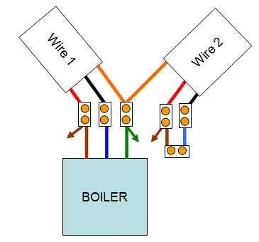
In need of advice/help please. Our gas boiler is wired as per the attached diagram. Boiler is controlled by a basic programmable timer which can run the CH and/or HW. Timer works fine in this respect and CH and HW both working fine.

The problem we have is that the boiler seems to have a permanent live feed - as even when timer programme positions are off, the boiler fires up for about 2 or 3 minutes every 15-20 minutes or so. Doesn't seem right to me - it's annoying and will also be using up gas.

I don't understand the attached wiring - the arrows in the diagram are wires off that have been cut but perhaps were once connected to a thermo/frost stat. Wire colours are as shown in the diagram.

Any help or advice much appreciated - easy fix or get a sparky in?

Thanks you in advance. J

 
Sponsored Links
Unlikely a sparky will be of much use, but without knowing what boiler you have and the controls fitted to it we can't be of much use either.
 
Thanks. Boiler is an Ideal Classic FF 380. Sorry I can't be of more help with regard to more specific information. The wiring diagram shown is the only wiring that is external to the boiler if that helps?

J
 
To get independent control of CH and HW from a single boiler, you must have one or more electrically operated valves somewhere or, just possibly, two pumps. Time for some detective work. :) :) :)

1) When you call for CH only, a pump will run somewhere. Can you find it?

2) When you call for HW only, does the same pump run? Or a different one? Or none at all?
 
Sponsored Links
Well that's a pretty standard setup with a single pump and a 3-port valve and I would expect the boiler to come on only when needed. It sounds like yours is permanently on and it's cycling on and off on its own internal thermostat.

Some boilers need a permanent live supply to power the pump for a timed run-on period after the gas goes off. They will have at least five terminals: permanent live, switched live in (for the gas valve), switched live out (for the pump), neutral and earth. The last two might be duplicated for ease of wiring.

You show a diagram with five terminals altogether but the two on the right don't appear to connect to anything. :confused: :confused: :confused: Can you provide any extra information, like labels on the terminals? Are there any more terminals with no wires in them? Can you see where those two external cables go? :?: :?: :?:
 
Thanks Space cat

It sounds like yours is permanently on and it's cycling on and off on its own internal thermostat.
That's what I think too.

Can you provide any extra information, like labels on the terminals? Are there any more terminals with no wires in them? Can you see where those two external cables go?
There aren't any labels on the terminals and I can't see where the two external wires go I'm sorry.

I agree it is odd that wire 2 is not connected to anything. Only other clue is that cut wires that hang off terminals 1, 3 and 4 (as in the diagram). Two are coloured brown, the other earth. I'm assuming that these were once connected to something - was thinking a frost stat or something. I hope that helps trigger something with someone otherwise I'll just have to get a sparky who can do heating wiring.

J
 

DIYnot Local

Staff member

If you need to find a tradesperson to get your job done, please try our local search below, or if you are doing it yourself you can find suppliers local to you.

Select the supplier or trade you require, enter your location to begin your search.


Are you a trade or supplier? You can create your listing free at DIYnot Local

 
Back
Top