
You are using an out of date browser. It may not display this or other websites correctly.
You should upgrade or use an alternative browser.
You should upgrade or use an alternative browser.
Zanussi ZWD 1472 W Washing Machine Fault E51
- Thread starter Ed2257J
- Start date
- Joined
- 5 Jan 2014
- Messages
- 18
- Reaction score
- 0
- Country

Well, I have an update, if I was a doctor it would be a case of the operation was a success, but the patient died.
I replaced the resistor, caps and had already tested the nearby diodes
I have some more photos
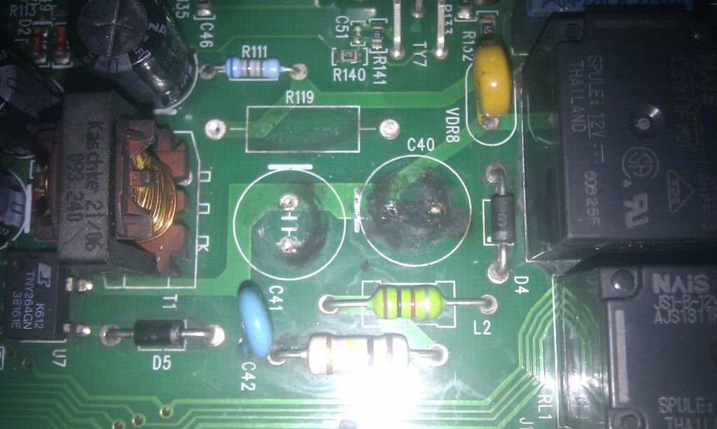
First, the board with the resistor and caps removed, so you can see the carbon deposits
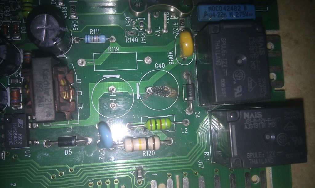
Then, the board after cleaning, showing some erosion of the board
I put the new components in, having made sure that each of the connection points had continuity to the right part of the board.
The machine was reassembled, powered on, and the machine was alive, with all the buttons and the display working correctly.
I then decided to run a final test by running through a wash program. the door locked, there was the sound of the discharge pump making sure the drum was empty and then after about 2 seconds a bright blue flash and bang.
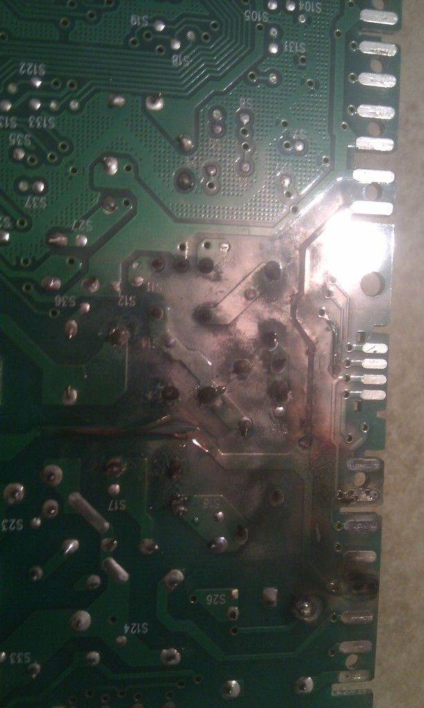
The underside of the PCB is now fried but there's no real sign of damage to the top of the board.
and
Thanks for all the help, unfortunately on this occasion it looks like I have not been successful in my repair attempt. I don't think I did anything wrong, but it's always possible that I did.
I'm now on the lookout for a s/h PCB, but suspect I'm going to have to buy a new washer/dryer imminently before we run out of clean clothes.
Hopefully the additions to the original thread will be helpful for others. The service on the components I ordered on ebay was superb - shipped within the hour and next day arrival.
Thanks again
I replaced the resistor, caps and had already tested the nearby diodes
I have some more photos
First, the board with the resistor and caps removed, so you can see the carbon deposits
Then, the board after cleaning, showing some erosion of the board
I put the new components in, having made sure that each of the connection points had continuity to the right part of the board.
The machine was reassembled, powered on, and the machine was alive, with all the buttons and the display working correctly.
I then decided to run a final test by running through a wash program. the door locked, there was the sound of the discharge pump making sure the drum was empty and then after about 2 seconds a bright blue flash and bang.
The underside of the PCB is now fried but there's no real sign of damage to the top of the board.
and
Thanks for all the help, unfortunately on this occasion it looks like I have not been successful in my repair attempt. I don't think I did anything wrong, but it's always possible that I did.
I'm now on the lookout for a s/h PCB, but suspect I'm going to have to buy a new washer/dryer imminently before we run out of clean clothes.
Hopefully the additions to the original thread will be helpful for others. The service on the components I ordered on ebay was superb - shipped within the hour and next day arrival.
Thanks again
- Joined
- 5 Jan 2014
- Messages
- 18
- Reaction score
- 0
- Country
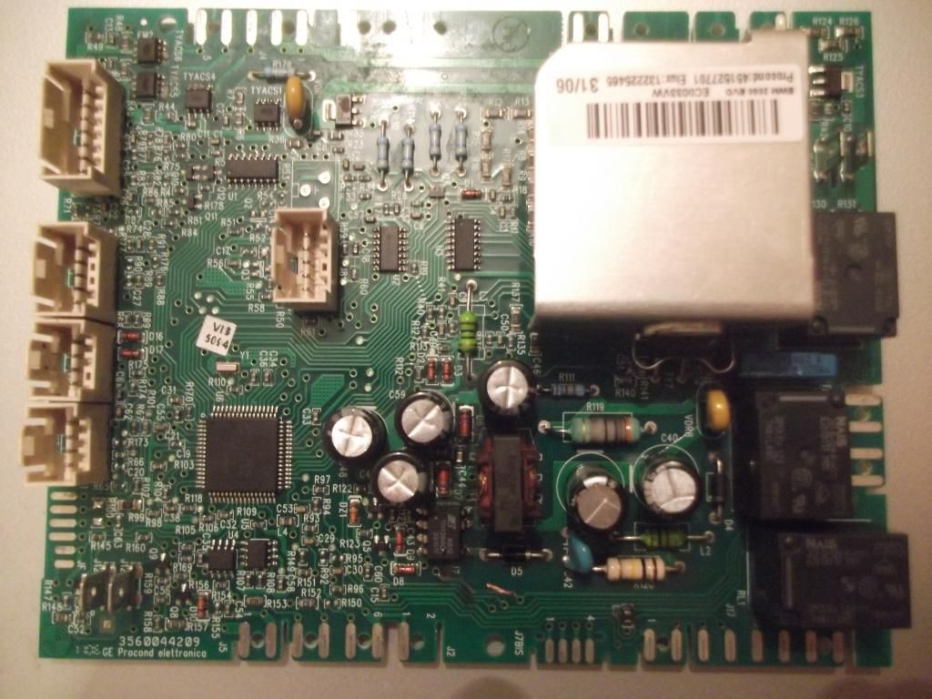
The sticker on the plastic cover says the following:
Procond Electronics
Type P.451527701 F:5684
Type E. 132225565
SW Ver W4C30127 02/Aug/06
The sticker on the heatsink has the same P number, Elux is 132225465 (slightly different) 31/06, which I guess is the week number. There is another series of numbers, in smaller text
EWM2000 Evo EC0033VW
Procond Electronics
Type P.451527701 F:5684
Type E. 132225565
SW Ver W4C30127 02/Aug/06
The sticker on the heatsink has the same P number, Elux is 132225465 (slightly different) 31/06, which I guess is the week number. There is another series of numbers, in smaller text
EWM2000 Evo EC0033VW
Should have known I wouldn't have one! Typical.
Is the board a simple single layer board? Tracks on bottom, components on top.
Or a multi-layer board? 2 or more track layers
Have to ask but do you think you could have re-connected the cable connectors wrong? Wrong way around or misaligned.
I can see the new caps were fitted correctly, polarity.
The resistor you replaced looks somewhat burnt out, odd. Test and see what reading you get, in cct should be ok. Also test one of the new resistors to see what reading you get, definately 33ohm?
So would you say at the point of motor kicking in or possibly heater it went BANG?
Whats the white stuff between L2 and R120? Wasn't there before!
- Joined
- 5 Jan 2014
- Messages
- 18
- Reaction score
- 0
- Country
You have very good eyesight....... and I suspect you have the experience yo know what exactly you are looking for. Turning to your questions
It's a multi layer board, the caps I replaced used the top and bottom layers. Whether there are more layers within the board I don't know.
I don't think that I put the connectors on incorrectly. I took photos before disassembly and with the notches on the board the connectors only want to go on the right way. If they are in the wrong place they won't push home. This was the main point I had in mind when I said I don't think I have made a mistake.
I have tested the R119 resistor. As you have probably already guessed, that has blown and is open circuit. It was 33 ohm (well 32.9) before fitting as are the others.
The start routine for this washer is
1. Solenoid locks the door
2. Discharge pump empties the drum / makes sure it is empty
3. Cold water fill by opening of inlet solenoid
4. Program starts
I would say it went bank approx 1-2 seconds after the discharge pump kicked in. That might mean it took a short period for the short to occur on the discharge pump, or the instant the inlet solenoid became live.
The white stuff between L2 and R120 wasn't there before and is like a crusty cement. I can't see where it has come from as there doesn't seem to be any damage to either component. R119 reads 98 ohms and L2 0.7ohms in circuit. I don't know if the picture shows it well enough, but one of the main copper tracks has lifted off the board substrate.
Thanks for looking for a board. I suspect that many Zanussi have the same board, the same components but with different software loaded
See if you can trace where the 33ohm resistor goes, solenoid, heater,motor
Also solder side of a relay coil joint looks blown.
I am quite sure looking at the board it is just a 2 layer, component side and solder side so should be simple to trace tracks and repair tracks (solder wires to relevant parts on the board).
Also solder side of a relay coil joint looks blown.
I am quite sure looking at the board it is just a 2 layer, component side and solder side so should be simple to trace tracks and repair tracks (solder wires to relevant parts on the board).
R120 - brown/black/yellow/gold 100kohm 5% tolerance
Of course can read different in cct due to other components so would need to lift one leg to test properly.
Check resistance of the coils on the relays.
Again check resistors and diodes and anything else to see if anything else is suspect.
Photos of the whole board, both sides would be good in high quality and in focus so I can zoom in and pan around.
Or each side in 2 halves slightly overlapping so I can easily match up.
- Joined
- 5 Jan 2014
- Messages
- 18
- Reaction score
- 0
- Country
I am trying to trace the wires from the connector that has scorched. It gous to the left rear of the machine, near the drum motor and discharge pump but because of the design of the casing with limited access I haven't been able to finish tracing them physically. I haven't been able to locate a service manual online to trace on paper either.
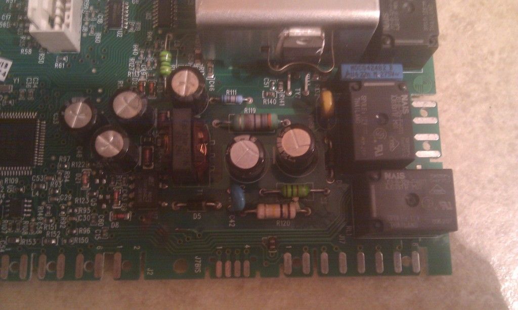
In the meantime I have uploaded a couple of hi-res photos - I think they will show large on the forum and you should get the full resolution.
I flipped the board along the long edge, and the scorched area relates to the area between the transformer on the left to the relays on the right and below the power transistor
Above R35 is what looks like a voltage regulator but could well be an A.C line swither (3 legs on one side and 1 leg on the other), is that dirt on top or a chip out of it, possibly blown. Could just be a heat mark and nothing to worry about.
- Joined
- 5 Jan 2014
- Messages
- 18
- Reaction score
- 0
- Country
I think what you saw was a digital artifact, an exaggerated view of reality. The component ref is TYACS2, there was a mark on it but a quick wet oif the finger removed it so suspect it was a watermark.
You were correct about R120, it's 94k ohm resistance. When i was 8 I knew all the colour codes by heart, but the years and a new colour code system mean I have to look it up these days and I forgot what setting the meter was moved to.
Having looked at the board I can see the following issues:
Topside first
The track from just below D5 has been exposed / evaporated towards U7
Possible heat marks on the two tracks below
R119 blown
L5 looks like it has heat residues around it
Light green material deposit to left of L3
Bottom layer
Connector strip 4 (from right) evaporated
Track from connector 4 raised from substrate but still has continuity
Heat scorching on underside of RL1 (top left)
Heat scorching over that whole area of the board
Greater blackening of the solder joins under C41 - I'm still using lead/tin solder
Damage to pin 7 - looks like solder addition ???
Evaporation of the trac from pin 13 to point where it meets track 4, just below R120
Removal of shellac/varnish from pin 10 to connector to top layer, where damage continues
I don't know what component an "L" is - it looks like a resistor, but must be something else, or a special type ?
- Joined
- 5 Jan 2014
- Messages
- 18
- Reaction score
- 0
- Country
It's a vintage 2006/07 machine so is wholly electronic, no mechanical timer
There are three relays under the heatsink, and you can see the heavy tracks on the underside of the board.
The heatsink itself is solely for what I thought was a power / mofset transistor but having removed the retaining clip is actually a triac part number BTB16-7008W
http://pdf.datasheetcatalog.com/datasheet2/3/07ppp3itec4990y9w6wk7zaierwy.pdf
Ok just thought water could have got into timer, not a good mix.
Have you checked the front fascia control panel board looks ok.
Have you systematically meter checked heater/motor/solenoid etc.. dried them out with a hair dryer. Checked wiring connections are dry.
Have you checked the front fascia control panel board looks ok.
Have you systematically meter checked heater/motor/solenoid etc.. dried them out with a hair dryer. Checked wiring connections are dry.
DIYnot Local
Staff member
If you need to find a tradesperson to get your job done, please try our local search below, or if you are doing it yourself you can find suppliers local to you.
Select the supplier or trade you require, enter your location to begin your search.
Please select a service and enter a location to continue...
Are you a trade or supplier? You can create your listing free at DIYnot Local
Similar threads
- Replies
- 0
- Views
- 3K
- Replies
- 0
- Views
- 1K