Hi all,
Just had some calcs done by an engineer for knocking through a cavity wall and I have a suspicion the resulting chunk of steel is for the benefit of his insurance premiums and not our interior design and ceiling height")
So am I correct in assuming, for a straighforward hole-in-the-wall where the beam is only holding up what's vertically placed on it...
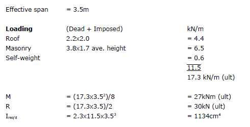
1) What really matters for the beam itself is the Second Moment of Area (I) calculation for the length of the beam, and that this number simply has to be less than the published value in the corus blue book for any beam.
( where I = 2.3 x total loading on beam x span ^2 )
2) If parallel flange channels are specified, two of them as it's a cavity wall, each beam will only have to support the weight on that leaf. Therefore the maximum beam depth will, in effect, be that beam which is supporting the outer leaf which is denser than the inner leaf. i.e. specifying each beam using weight of both inner and outer leaf is incorrect - or should I say overengineered ?
Thanks for any assistance.
Just had some calcs done by an engineer for knocking through a cavity wall and I have a suspicion the resulting chunk of steel is for the benefit of his insurance premiums and not our interior design and ceiling height
So am I correct in assuming, for a straighforward hole-in-the-wall where the beam is only holding up what's vertically placed on it...
1) What really matters for the beam itself is the Second Moment of Area (I) calculation for the length of the beam, and that this number simply has to be less than the published value in the corus blue book for any beam.
( where I = 2.3 x total loading on beam x span ^2 )
2) If parallel flange channels are specified, two of them as it's a cavity wall, each beam will only have to support the weight on that leaf. Therefore the maximum beam depth will, in effect, be that beam which is supporting the outer leaf which is denser than the inner leaf. i.e. specifying each beam using weight of both inner and outer leaf is incorrect - or should I say overengineered ?
Thanks for any assistance.