ring final continuity test ??

Joined
3 Dec 2010
Messages
71
Reaction score
0
Country
United Kingdom
Hello,

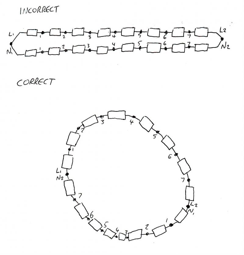
im just reading a book just now and there is something ive just read about the ring final continuity test i dont understand, say when u cross the live to the neutral of the same cable and not the opposite neutral the books says " that the resistance will start to go higher as u measure at the sockets the further u go away from the CU?

why does that happen?
 
Sponsored Links
Because the length of conductors whose resistance you are measuring is increasing the further away from the consumer unit you go: resistance is proportional to length.

It does not happen when the phase and neutral from the opposite cables are connected because you should be measuring the resistance of the same length of conductor at each point.
 
Your terminology isn't great but I'll give it a shot.

A ring has two legs. We'll call them leg 1 and leg 2, and therefore L1, N1, L2, N2 for the line & neutral conductors.

Think about what happens if you connect L1 and N1 together and start testing at socket outlets. To make things easier, we'll say that 1m of 2.5mm² conductor has a resistance of 1Ohm (it's much, much less than this btw). The closest socket to the CU will have the lowest resistance, simply because it's the shortest distance. Lets say the first socket is 1m from the CU.

From 1 probe, down L1, back up N1 and into the 2nd probe on your test meter is 2m, so using our fictional values the meter will give a reading of roughly 2Ohms (plus a few milli Ohms due to the resistance of connections, test probes etc). Next socket, let's say 3m from the CU. Again, down L1, back up N1, 3 * 2 * 1 = 6Ohms, and so on and so forth.

Connecting L1 with N2 and L2 with N1 means that wherever you are on the circuit, the loop from 1 probe to the other is equal distance, thus giving equal readings.

HTH.

Edit: If I remember correctly readings should be within 0.05Ohms of each other (or am I thinking of something else?)
 
Connecting L1 with N2 and L2 with N1 means that wherever you are on the circuit, the loop from 1 probe to the other is equal distance, thus giving equal readings.

Is much clearer than what I wrote!
 
Sponsored Links
Your terminology isn't great but I'll give it a shot.

A ring has two legs. We'll call them leg 1 and leg 2, and therefore L1, N1, L2, N2 for the line & neutral conductors.

Think about what happens if you connect L1 and N1 together and start testing at socket outlets. To make things easier, we'll say that 1m of 2.5mm² conductor has a resistance of 1Ohm (it's much, much less than this btw). The closest socket to the CU will have the lowest resistance, simply because it's the shortest distance. Lets say the first socket is 1m from the CU.

From 1 probe, down L1, back up N1 and into the 2nd probe on your test meter is 2m, so using our fictional values the meter will give a reading of roughly 2Ohms (plus a few milli Ohms due to the resistance of connections, test probes etc). Next socket, let's say 3m from the CU. Again, down L1, back up N1, 3 * 2 * 1 = 6Ohms, and so on and so forth.

Connecting L1 with N2 and L2 with N1 means that wherever you are on the circuit, the loop from 1 probe to the other is equal distance, thus giving equal readings.

HTH.

Edit: If I remember correctly readings should be within 0.05Ohms of each other (or am I thinking of something else?)

ok but why does the cores not be at equal distance if your connecting the same live and neutral of the same cable to each other and when u cross them over on each other they are at equal distance?
 
ok but why does the cores not be at equal distance if your connecting the same live and neutral of the same cable to each other and when u cross them over on each other they are at equal distance?

Because if you connect L1 to N1 and L2 to N2 your meter will measure the path of lowest resistance. So it'll be a low reading near the CU as it's going up & down L1 and N1, once you get to the middle you'll get your highest reading as it's the furthest distance to L1 and N1 as well as L2 and N2. Once you start getting closer to the CU the path of lowest resistance will be up & down L2 and N2.

When you cross them over, you're effectively forming a loop of the entire ring. Lets say the ring is 50m long. Starting at socket 1 again, it's 1m down L1, but that's connected to N2, which has to go all the way around the ring - 49m, giving a fictional reading of 50Ohms. Socket 2 was 3m from the CU. Again, it's 3m down L1 but that's connected to N2, which has to go the long way around - 47m, giving - yep, 50Ohms.

Basically leg 1 is connected to the first socket and leg 2 the last. By connecting L1 and N2 you're reading the entire loop - up L1, through the CU, down N2, back through all other sockets on the ring to the same socket that you've connected your probes to.

and also if the same cable was connected to each other L1-N1 and L2-N2 that is double the distance that has to measured yea?
 
You have to consider what you are trying to achieve by the interconnections. Below is a (badly drawn) schematic of the two interconnections.
For simplicity reasons I will use 1 ohm for each resistor, however in reality on a ring final circuit each resistance will be a fraction of this and not equal but the theory is the same.
In terms of R1 and Rn as the cores are of the same length and CSA the resistance of the conductors of each run should be equal hence both the resistors between nodes 1 and nodes 2 are of equal value, similarly with the resistors between nodes 2&3, 3&4 etc.

With the incorrect version if you take a measurement between nodes 1 you will have two resistances in parallel, 2Ω to the left and 14Ω to the right. As these are in parallel the overall resistance will be (2x14)/(2+14)=1.75Ω.
If we move along to nodes 2 and measure the resistance the result will be (4x12)/(4+12) = 3Ω
nodes 3
(6x10)/(6+10) = 3.75Ω
nodes 4
(8x8)/(8+8) = 4Ω
nodes 5
(10x6)/(10+6) = 3.75Ω
nodes 6
(12x4)/(12+4) = 3Ω
nodes 7
(14x2)/(14+2)=1.75Ω

As you can see from above, the resistance increases towards the centre.

For the correct version the measurement across nodes 1 will give two lots of 8 ohms in parallel. This will give you (8x8)/(8+8)=4Ω
The measurement across nodes 2 will also give you the same (8x8)/(8+8)=4Ω, similarly for all the rest and the same as checking across the interconnections at the CU.

You can try this with varyring resistances around the ring (keeping the resistances of equal values or proportional between the nodes) if you wish.
 
And this is why radials are better.

If you use that logic on other things then a 1950's car is better than a 1990's car. Better only because it less complicated and therefore easier to test and repair.

Yes. but any car from 2000 onwards is easily plugged in and tested, it isn't even intrusive. Motor vehicles aside we are talking about wiring which has mostly stayed the same, it hasn't become more developed, sophisticated or more efficient between 1950 and 1990, the sceince is the same. What has happened though is that in that time frame millions of ring final circuits have been poorly installed and badly modified. I think that logic is best used on a ring final circuit, not so much on the MASSIVE advancments in automotive engineering. You cannot really apply it to the advancments in medicine either as we are keeping onder people alive for longer. I cant think of anything to compare it to for an analogy which suits it as there is nothing else about which was poorly designed from the outset with the only option to improove it being to abolish it, but adopted and held in such high regard by people who didn't understand it.

I dont want to start a long argument or a 4 page thread about ring vs radial, my veiws are that radials are alot safer and superior, they are quicker to install, easier to commision and test and easier to fault find on, they are much safer in as much as it is harder for them to be incorrectly installed or altered. A fault on a 'live' conductor will make it's self shown and known to the user of the installation and will not leave the installation still functioning except in a dangerous situation. Anywhere a ring final circuit is can be fed from the same amount or cable with 2 x 20A mcbs or less 4mm2 cable on a 32A breaker.
 
How very sad...

:rolleyes: :rolleyes: :rolleyes:

He's right though. This is an internet forum, not a text message. There's no need for lack of grammar or 'txt tlk'. To be an electrician you need to have a reasonable understanding of the English language and if you're asking a question on an internet forum it's only polite to use good English.
 

DIYnot Local

Staff member

If you need to find a tradesperson to get your job done, please try our local search below, or if you are doing it yourself you can find suppliers local to you.

Select the supplier or trade you require, enter your location to begin your search.


Are you a trade or supplier? You can create your listing free at DIYnot Local

 
Sponsored Links
Back
Top