Just as I said before, you again seem to be assuming that the 20mA current flowing through your N/E resistor will flow through the N side of teh RCD - but it won't.
But are you sure it won't? because that is the source of my confusion, it's just taken me a while to get there

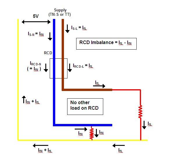
If there is a 5V PD between N and E from the supply (TN-S system) as I described why won't the current flow between N and E? Again, I'm not saying that I am right but it seems to me that it should cause a N - E current.
Right. I think that long last realised why we have been talking at cross-purposes! I'm not sure if you said this explicitly before, but I see you now write:
If there is a 5V PD between N and E from the supply
If that is the case, then I have to agree with you that a current due to introducing a N-E path (fault) within the installation
will flow through the N side of the RCD and therefore will (***in the absence of other factors - see below), as you have been persistently saying, have the effect of reducing the L-N imbalance in the RCD in response to an L-E fault - i.e. as you have been saying all along, the N-E fault would (subject to ***) have the effect of increasing the L-E fault threshold of the RCD.
However, I've been talking/thinking about the situation (as with TN-C-S) in which there is essentially no potential difference between the supply neutral and 'earth' (which in this context refers to the installations CPCs and bonded metal etc.). As I said (and which probably confused you, if you were thinking of a pd between neutral and earth), in the absence of any loads on the installation, introducing a N-E fault then has no effect. However, if there are loads resulting in current through the RCD, introducing a N-E fault will provide a partial return path for the load current which bypasses the N side of the RCD, so that the current in the N side of the RCD will
reduce as a result of the N-E fault - with all the consequences I've stated which have been confusing you!
*** So, with a pd between incoming neutral and 'earth' (as quite possible with TN-S and TT), but no loads on circuits supplied by the RCD, the effect of a N-E fault will be to
increase current through the N side of the RCD. If, on the other hand (as with TN-C-S), there is no pd between incoming N & 'E', but there are loads being supplied by the RCD, then the effect of an N-E fault will be to
reduce current through the N side of the RCD. If (probably the real-word situation with TN-S or TT), we have both of those things going on (pd between incoming N&E AND loads on the RCD), then whether an N-E fault increases current through N side of RCD (hence increasing threshold for L-E faults trips) or decreases current through N side of RCD (hence decreasing threshold for L-E fault trips) will
depend upon which of those two opposing processes wins - the greater the load on RCD-supplied circuits, the more likely that 'my', rather than 'your', situation will prevail. With TN-C-S, I think that I probably 'win' all the time, provided there is at least some load being supplied by the RCD.
So ... as with so many things in life, it seems like 'it depends'!
Have we perhaps (almost?) got there?
")
Kind Regards, John.


")