

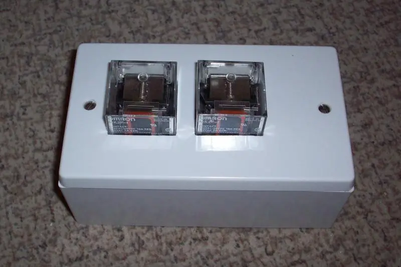
We touched on this a few months ago. I've been experimenting with various ways of housing octal plug-in relays, in situations in which I ideally don't want to have to use a large enough enclosure to totally 'enclose' them (and thereby also totally deprive them of ventillation/cooling) - so I wonder what people think about have the ends of them 'exposed'. For example, one of the experiments is:
Kind Regards, John.
Kind Regards, John.

 but neat.
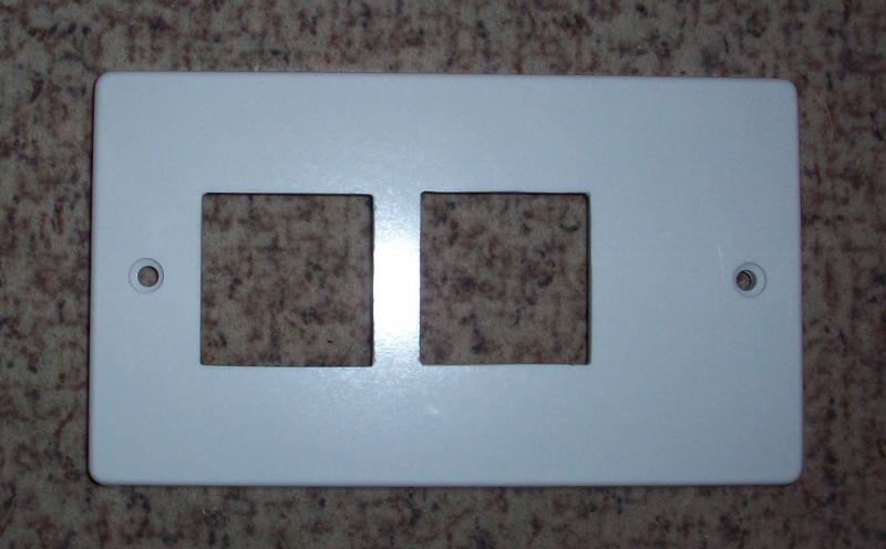
")