
You are using an out of date browser. It may not display this or other websites correctly.
You should upgrade or use an alternative browser.
You should upgrade or use an alternative browser.
Sub main query
- Thread starter JonathanA
- Start date

I know that terminating that SWA in the KMF will be a real pig! but hey ..
IOt isn't made to terminate SWA, as you probably know.
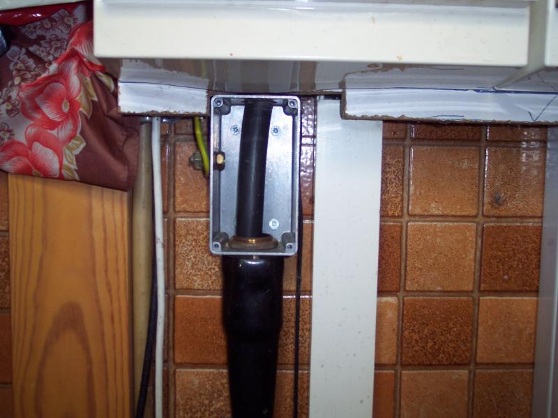
Use a galv box below the KMF and terminate the gland on that. Pass the conductors through to the KMF. Buy a set of cable shrouds with the KMF for the meter tails side.
Fair enough.Thanks John, I think I'm sold on that 80A KMF switch fuse at the supply end and a DP 63A MCB at the studio end.
You can't do that. You need to terminate the SWA into some sort of box and then take 16mm² double-insulated singles from there into the switch-fuse.I know that terminating that SWA in the KMF will be a real pig!
Kind Regards, John ²
It's not quite as simple as that with the KMF, since you need to separate out the conductors for separate entry into the KMF. However, it's not that difficult to find a way of doing it.
Kind Regards, John
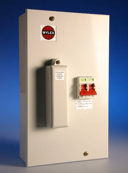
They make switch fuses in metal clad these days.  The more I'm reading here the more I get the feeling the OP is well out of his depth with this job.
The more I'm reading here the more I get the feeling the OP is well out of his depth with this job.They do. In fact, the issue often is in finding one which isn't metal!They make switch fuses in metal clad these days.
You could well be right. Furthermore, the forum police must be asleep or distracted, since I've yet to see any mention of electricians, the signing of declarations on certificates or of notification of a job which will inevitably involve the installation of 'new circuit(s)'The more I'm reading here the more I get the feeling the OP is well out of his depth with this job.
")
Kind Regards, John
Wylex metal clad 100amp sw fuse with 80amp fuse fitted.
The KMF is for tails, or T&E/split con with the additional clip on shroud. Wouldn't go near one with SWA.
The KMF is for tails, or T&E/split con with the additional clip on shroud. Wouldn't go near one with SWA.

True. I suppose it's my fault for mentioning the KMF, which i did because the OP seemed concerned about size. Mind you, I make no apologies for advocating a switch-fuse, rather than attempting to originate this substantial sub-main from a CU (even if that did mean a KMF plus another box!)!The KMF is for tails, or T&E/split con with the additional clip on shroud. Wouldn't go near one with SWA.
Kind Regards, John

3 pages and still no mention of what the actual loads in this 'studio' will be, or any existing loads in the garage where the supply will be taken from.
Or if this:
Or if this:
is really a 100A supply or just one which happens to have a fuse carrier marked with 100A.I have a 100A PME supply to a garage
Even if the garage really is a 100A supply, 80A being used for a submain leaves very little for the existing circuits.The SWA cable has a maximum rating of 91A and I designed the installation on this basis. I realise now that the cable won't be able to take this load in practice and I think I will have to downgrade the design load from 80A to say 63A.
Volt drop is with reference to the nominal voltage of the installation/supply.
Lots of 240V supplies out there with nominal voltage which never gets to 230V on a winter's night at Christmas with no gas on the street.
Conversely plenty I bet designed to 3% thinking terrific but with 230V -6% coming from supplier.
You need to understand the characteristics of your supply and load equipment before deciding whether to throw the whole lot/reinforce it with another cable.
View media item 66091
Lots of 240V supplies out there with nominal voltage which never gets to 230V on a winter's night at Christmas with no gas on the street.
Conversely plenty I bet designed to 3% thinking terrific but with 230V -6% coming from supplier.
You need to understand the characteristics of your supply and load equipment before deciding whether to throw the whole lot/reinforce it with another cable.
Yes, like this (slit between holes if someone asks).It's not quite as simple as that with the KMF, since you need to separate out the conductors for separate entry into the KMF.
View media item 66091
Why bother prattling with boxes and slits when you can just fit a switch fuse which is intended for the job? Footprint is similar.
This doesn't seem the right way round. You calculate the load and then the minimum size for the protective device. This is used to calculate the size of the cable. As for the thread, if the OP is an electrician, he is out of his depth.Quite apart from the (probably limiting) issue of voltage drop to which RF has referred, in design terms you appear to be approaching this issue somewhat 'back-to-front'. The 'design load/current' should be the actual required load (or, at least, an estimate thereof). The cable is then required to have a CCC at least as great as that design load, and, in turn, the device protecting that cable has to have an In no higher than that CCC.
Kind Regards, John
DIYnot Local
Staff member
If you need to find a tradesperson to get your job done, please try our local search below, or if you are doing it yourself you can find suppliers local to you.
Select the supplier or trade you require, enter your location to begin your search.
Please select a service and enter a location to continue...
Are you a trade or supplier? You can create your listing free at DIYnot Local