Brickwork over External Bifold Steel beam

Joined
14 Aug 2019
Messages
3
Reaction score
0
Country
United Kingdom
Hi Experts,
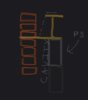
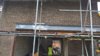
I need some guidance on covering an external beam which builders have installed for rear bifolds. The beam is 305x305 in the external cavity wall as shown in the attached pic. The beam is above the ceiling level of ground floor.

The architect suggested that there should be a brick layer outside(drawing) but the brickie has never done this before - He hasn't got a clue on how the bricks could adhere within the cavity of steel beam ? Is this quite a standard stuff bricklayers would do or am I being sandwiched unnecessarily between the two? The brickie is suggesting we cover it with PVC material of bifolds and stuff insulation but I cannot see it offering u value similar to an external cavity wall.

Also, would it need stuffing the insulation both on inner and outer cavities of the beam.
Kind regards
Viz
 

Attachments

  • External brick.jpg
    External brick.jpg
    120.8 KB · Views: 3,042
  • external bifold beam.jpg
    external bifold beam.jpg
    261.7 KB · Views: 8,146
Sponsored Links
That is a dreadful, unworkable detail. Ask the architect how the bricklayer is supposed to cut a slot out of the bricks to fit over the top flange. And also ask him/her about the lack of a cavity tray; water will seep down the inner face of the outer skin, pool over the top of the beam, cause rust-expansion long term, and will stain the brickwork below.
The correct way would have been to use an 'I' beam over the inner skin, with welded plate underneath to support the outer skin. Whoever did that detail knows the square root of nothing about the practical side of building.
 
Thanks Tony - appreciate what you are saying - the drawing was sent by the architects intern and I can see the issues with it. What is the best recourse from this point onwards ? I'd want to avoid putting an aluminium cladding to cover the beam as it will be quite chunky 300-400 mm. Is there a practical solution on achieving the brick cladding somehow from the situation we are in?
 
1. You need to check if the builder has included a cavity tray above the beam - one doesn't seem to be on the drawing. Hopefully he has used common sense and put one in.
2. No matter how you arrange the brickwork if you attempt to brick up between the flanges, it will remain unstable as there will be no effective bond, you will be left with 2 or 3 courses of loose brick and it will collect water behind.
Unless someone else comes up with a novel solution, I suspect you may end up having to clad the beam in metal to match the bifolds.
(this is how it is usually done).
2019-08-14_165654.jpg
 
Sponsored Links
Omg, a **** architect and a thick bricklayer equals a heap of ****e and not a clue between them.

Cement board, brick slips and a better bricklayer.

Btw, there is not even a cavity tray in that detail FFS. o_O:eek: That's no bricklayer or architect. Get on to trading standards as they are trading under false names.
 
Even if the drawing was done by the office junior ,and it was certainly done by somebody incompetent, the architect is still responsible for drawings going out of their office. Apart from the terrible detailing pointed out by others ,why are they showing the inner leaf of blockwork in 75mm course heights, it shows a lack of technical knowledge in everything about it ? You should go back to the architect ( if they are an architect :!: ) and express your concern, mentioning the points raised on here and ask them to sort it out.
 
We are trying to move on from the incompetent design and implementation outputs and trying to fix this as efficiently as possible.

So not much point going back to architects when we know they haven't got much practical experience. So they'd potentially introduce more problems.

Moving on, Is a 20 mm brick slip over 9mm cement board attached to timber (bolted to steel) way forward for me then?
I can find out about the cavity tray but incase it has not been installed, should I get be able to get it fitted retrospectively or are there any alternatives to that?
 
Woody's suggestion of brick slips glued on cement board might be a compromise way forward, but you might have problems getting the courses right.
If lining up the brick courses is a problem, consider arranging them as soldiers (upright bricks) and then a normal course of flat bricks. The solidiers could be cut to a height to suit the brick coursing. The bottom plate of the splice might be a problem, in which case the cement board would need to be taken down to cover that.
For the cavity tray, it can be fitted retrospectively but would involve supporting the outer skin on strongboys, taking out two or three courses along the top of the beam, fixing the dpc to the inner leaf and then bricking back up, leaving a few weepholes. This would be a pig of a job but if not done there is a real risk of water pooling on top of the beam and getting in over the door frame.
2019-08-14_200011.jpg
 
Woody's suggestion of brick slips glued on cement board might be a compromise way forward, but you might have problems getting the courses right.
If lining up the brick courses is a problem, consider arranging them as soldiers (upright bricks) and then a normal course of flat bricks. The solidiers could be cut to a height to suit the brick coursing. The bottom plate of the splice might be a problem, in which case the cement board would need to be taken down to cover that.
For the cavity tray, it can be fitted retrospectively but would involve supporting the outer skin on strongboys, taking out two or three courses along the top of the beam, fixing the dpc to the inner leaf and then bricking back up, leaving a few weepholes. This would be a pig of a job but if not done there is a real risk of water pooling on top of the beam and getting in over the door frame.View attachment 169511

The steel seems to be 300mm high, so will work courses.

I've also noticed the detailing of the post, the way the bricks finish short and the bolts and cleat at the top. So fitting the new door frame will be fun. Looks like the engineer went to the same school as the rest of them. :cautious:
 
If it's one of the 305 column sections, its depth will actually be 308mm, which might cause a coursing problem - this might be overcome by using soldiers cut to an approproate length.

The edge of the flange looks to be set back from the face of the brickwork, but would the set-back be sufficient to accomodate 20mm slips + board + adhesive?
Hopefully the slips wouldn't finish proud of the main brickwork.

And yes, the splice plate is a problem. As the splice is near the end of the span, the bending moment won't be too high and I suspect thinner plates could have been used; the bolt heads would still stick down.
This is a case of different designers not communicating.
 
Are Building Control involved on this job ,they should be :?: If they are ,are they checking the work on site :?: Who is dealing with building control to ensure compliance with building regulations :?:
 
So not much point going back to architects when we know they haven't got much practical experience. So they'd potentially introduce more problems.
Very strange ,even a newly qualified architect wouldn't produce construction details like that :!: Are you going to accept responsibility now for this complying with bldg. regs :?:
 
I did 1 or 2 almost like this when the engineer designed a similar steel beam over an opening in an external wall , with cavity tray and weep vents at 450mm centres over the steelwork of course , the detail was similar to Tony1851's last sketch but with 25mm thick hardwood board facing instead of brick slips and a lead flashing dressed over the top of the hardwood and turned over the top of the steel and under the dpc tray.
p.s. see oak rsj covers on 'oak by design' website for this sort of thing re steel beam casings.
 
Last edited by a moderator:
1. You need to check if the builder has included a cavity tray above the beam - one doesn't seem to be on the drawing. Hopefully he has used common sense and put one in.
2. No matter how you arrange the brickwork if you attempt to brick up between the flanges, it will remain unstable as there will be no effective bond, you will be left with 2 or 3 courses of loose brick and it will collect water behind.
Unless someone else comes up with a novel solution, I suspect you may end up having to clad the beam in metal to match the bifolds.
(this is how it is usually done).View attachment 169502
Hi Tony, I know this is an old thread and my question does not benefit the OP in any way but I have a question that you may be able to answer for me.

I have a single storey extension going in with a 4m long bifold to the garden, it is likely that due to this span we would be installing this steel with welded plate as you’ve shown in your detail drawing. My question is:

Where this steel is supported at either side of the bifold, will the padstone simply be on the inner leaf? As the welded late is there to support the outer leaf of bricks and is not relying on the external bricks below as a load wall?

hope you understood. Here a sketch I’ve done if it helps, it’s a detail of the steel at the supporting wall at either side of the bifold.
 

Attachments

  • 8284DC7F-20CB-4C64-8D38-E9F97DD49AD5.jpeg
    8284DC7F-20CB-4C64-8D38-E9F97DD49AD5.jpeg
    146.7 KB · Views: 852
Hi,
The plate usually goes end-to-end of the I-beam , so that there is equal length of plate on inner and outer skins.
If the bearing is of reasonable length, there should be no need of a padstone on the outer brick skin - which would look naff anyway.
If the inner skin is aerated block, you would need a padstone there.
 

DIYnot Local

Staff member

If you need to find a tradesperson to get your job done, please try our local search below, or if you are doing it yourself you can find suppliers local to you.

Select the supplier or trade you require, enter your location to begin your search.


Are you a trade or supplier? You can create your listing free at DIYnot Local

 
Sponsored Links
Back
Top