Builder has done this ……

Joined
25 May 2021
Messages
7
Reaction score
0
Country
United Kingdom
Hi all

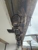
So I’m having 3 meter bifold doors installed in my new build. The whole needed widening from 2 meters to 3. I had the engineer do calculations and we had the steel fabricated. Because of a stock issue the steel had to be made slightly higher than it was originally because we had a deadline to meet and couldn’t wait for stock. The engineer signed this off and said the new height is sound.

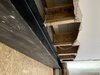
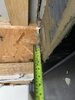
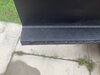
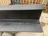
The builder has installed the steel BUT in the process, to allow for the I-beam joists to sit on the steel he has cut the corners off and moved the flange from the bottom onto the horizontal of the new cut. See pictures.

The engineer has said this is a big no no and very dangerous. The manufacturer also stated this. I’m now left with a situation where I need to have these repaired or replaced. The builder will most certainly get the bill.

I have asked the engineer about fixing in a timber through the inner leaf brickwork across the wall above the steel (it will overhang the steel a little) to hang the joists off but he advised this will create too much eccentricity. I don’t understand this because joists are hung from timber with hangers every day. All we would be doing is cutting the I-beam back to its original profile essentially shortening it, then hanging it.

Does anyone have any idea how these can be repaired so that the load is transferred correctly? Any ideas ?

Thanks.
 

Attachments

  • 1D9B5559-9539-41A5-A568-D47FDC9DAE64.jpeg
    1D9B5559-9539-41A5-A568-D47FDC9DAE64.jpeg
    220.2 KB · Views: 370
  • D3104E69-F034-4006-AB3E-28A7AB0CD162.jpeg
    D3104E69-F034-4006-AB3E-28A7AB0CD162.jpeg
    282 KB · Views: 368
  • FE3ADC7C-E8EA-4C39-BFC9-7F9474A84D25.jpeg
    FE3ADC7C-E8EA-4C39-BFC9-7F9474A84D25.jpeg
    310.2 KB · Views: 370
Sponsored Links
If the engineer "signed this off" what was the revised detail for supporting the timber joists?

I think the engineer and/or architectural designer should carry a large part of the responsibility here. You cannot just specify a steel beam and not take into account how other structural elements will be supported.
 
1. What section-size is the steel beam?

2. Has a plate been welded underneath it to carry the outer skin?

In mentioning eccentricity, the SE is concerned about the torsion effect on the beam, which adds to the stress. But on a 3m span, torsion should not be too much of a problem. Has he done any figures on this to check, or did he just give an opinion?

Thanks for the reply.

1 the beam is large. I don’t know the exact section size. I have attached a picture of it. The steel is 30cm wide by 3300 long.

2. Yes there is a plate to support the outer leaf.
3. He has just gave an opinion so far a deeper investigation will be needed if I can’t find a solution.
 

Attachments

  • 71BA0202-9485-4650-B6F6-308D9F9B94A7.jpeg
    71BA0202-9485-4650-B6F6-308D9F9B94A7.jpeg
    300.7 KB · Views: 186
  • FA258420-EBC6-45A9-8E98-F92AD2867A7E.jpeg
    FA258420-EBC6-45A9-8E98-F92AD2867A7E.jpeg
    276.2 KB · Views: 171
Sponsored Links
Difficult to judge the size from the pics; the section size and weight should be in the calcs.
 
Difficult to judge the size from the pics; the section size and weight should be in the calcs.

the calcs that were done was for a lintel not as high but due to lack of stock they had to call the engineer who had a look through their product list and picked a different height steel. So that’s why the steel has ended up higher than the ibeams. I didn’t think an engineer would make a mistake like that.

I have attached the original calcs. But the new beam is slightly higher.
 

Attachments

  • C3BE66DC-E6E2-466F-9194-822ACE6E63D6.jpeg
    C3BE66DC-E6E2-466F-9194-822ACE6E63D6.jpeg
    170.5 KB · Views: 106
It's easily remedied. Something along these lines.
 

Attachments

  • Dudek - I-BEAMS_eng.pdf
    400.5 KB · Views: 217
It's easily remedied. Something along these lines.

thanks Jed

I thought cutting into an ibeam is a no no . Would these remedies apply to the way he has cut out beams ? He’s essentially cut the bottom corner off the beams with the bottom flange overhanging the steel beam by about an in and half. How could I tie that into the steel now ? Would it need repairing first and then re cutting to tie in ?
Thanks.
 
A 203 x 203 x 60 UC (!!) for that span was a bonkers, rookie design to start with....

Do what jeds suggests, or fix a 50 thick timber along the blockwork and use joist hangers.
 
A 203 x 203 x 60 UC (!!) that span was a bonkers, rookie design to start with....

Do what jeds suggests, or fix a 50 thick timber along the blockwork and use joist hangers.

thanks Tony. At least I know I have options. I did think about the timber across the back with joist hangers but the engineer wasn’t convinced. That would make the most sense to me as we can then just cut the i beams back to their normal shape and essentially shorten them then hang them.

The blockwork sat on the lintel is the inner leaf and isn’t a full height of block due to the height of the beam. It’s about an inch lower in height. Would that make a difference when attaching said beam with hangers and what fixings would be best suited to hanging timber on a thermalite inner leaf ? I’ll have to open up the outside brickwork to get to the back of the thermalite to fasten is we need bolts.
Cheers.
 
Bolts into Thermalite/Celcon are a pain, but doubt you would need to go through the outer skin?
Consider some resin-fixed bolts or threaded bar.
 
Sharing some general comments, although probably too late.

  1. The torsion on the beam due to the eccentricity is not just about the torsional stiffness of the beam but also the rotational stiffness of the supports. If the beam is really stiff but not restrained at the supports against twisting then the beam can roll over, in theory. The engineer is required to check a design to a clear robust direct load path, however in reality many parts of the construction that were ignored by the engineer contribute to how it resists the load, even so these additional load paths should not be relied upon unless designed or clearly stated and communicated as the intended load path.
  2. The original beam size is too big but maybe not to the extent that some are thinking. Regarding strength it will be able to carry far higher loads, but for deflection it may only be a bit over designed. It depends what the specification of the bifold doors is. Some manufacturers state in their literature such tiny deflections that a massive beam is required. Some don't differentiate between the permanent and imposed loading, or the in-service deflections vs the construction and installation tolerance.
  3. The timber I-beam joists are proprietary products. The engineer can't design them as such. They are specified from a catalogue. Once they are messed around with, such as the original post, and a remedial solution is used who is liable for that solution? The solution given by Jed is sensible but that might come from another manufacturer (and so wouldn't be covered by them if things collapse, manufacturer requires strict adherence to the installation being to their guidance docs), and that diagram doesn't cover schematically for an issue where the end of the timber I-beam is notched. Building Control can't sign it off. Builder could take full responsibility for it, suggest a fix, implement it and be liable, both in a sense of being sued (civil law) and capable under H&S Act (criminal law). For the H&S Act the builder would take on the role of the "designer" in this case.
  4. Wessex101's point about the responsibility that the engineer and architect should take for the coordination is an interesting point. In a competitive market for their consultancy services they are often appointed on lowest price, not on best service. Funny old world. Seems the issue of sorting it out is left to the last person standing, i.e. the builder on site, to work it all out. Hats off to those managing to not make mistakes.
  5. As for a solution I favour the cutting the timber I-beam back and using a joist hanger, and for engineer to work through eccentricity issues.

thanks for the detailed response.

The engineer specified ply bonded to the web up to the bearing.

The manufacturer sent me the data on the i joists so I have sent the that to the engineer to see if it changes his solution.

I was advised by a specialist company that at the bearing the only force of concern is shear stress. They explained that the beam is designed to withstand bend at its centre point and the depth of beam is designed to withstand that forced. He said at the bearing it’s about shear force. He said that beams in some old grand buildings taper off thinner towards the bearing showing that the bearing can be smaller. So he actually advised we wouldn’t need anything and it could be left. But the engineer specified this to strengthen the bearing.
 
I was advised by a specialist company that at the bearing the only force of concern is shear stress. They explained that the beam is designed to withstand bend at its centre point and the depth of beam is designed to withstand that forced. He said at the bearing it’s about shear force. He said that beams in some old grand buildings taper off thinner towards the bearing showing that the bearing can be smaller. So he actually advised we wouldn’t need anything and it could be left. But the engineer specified this to strengthen the bearing.

Correct. Shear maximum at beam ends, and bending moment maximum at middle - this is for a simply supported uniformly loaded beam.

The notched beam still has to carry the shear. For short highly loaded beams the shear can govern the choice of the beam size, although most beams are long (relative to their depth) and the bending capacity governs the design. Meaning there should be plenty of shear capacity.

Still, the liability for the solution implemented has to be with someone. I too would definitely strengthen this.
 

DIYnot Local

Staff member

If you need to find a tradesperson to get your job done, please try our local search below, or if you are doing it yourself you can find suppliers local to you.

Select the supplier or trade you require, enter your location to begin your search.


Are you a trade or supplier? You can create your listing free at DIYnot Local

 
Sponsored Links
Back
Top