• Looking for a smarter way to manage your heating this winter? We’ve been testing the new Aqara Radiator Thermostat W600 to see how quiet, accurate and easy it is to use around the home. Click here read our review.

Wires clarity

Joined
20 Oct 2021
Messages
96
Reaction score
2
Country
United Kingdom
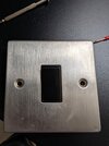
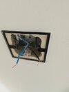
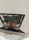
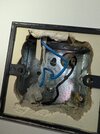
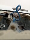
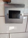
I want to switch a single switch to a single socket. On opening the plate, I found a black and blue wires both connected to a single plastic connector shown in picture. These were both inserted from the same end too. The wires come from different points into the box. Can someone advise which is live/neutral to connect to the socket or are they just L1 and L2 and there is no neutral coming into the box? In which case what can I do? Thanks.
 

Attachments

  • PXL_20250607_094117176.jpg
    PXL_20250607_094117176.jpg
    383.9 KB · Views: 56
  • PXL_20250607_094109028.jpg
    PXL_20250607_094109028.jpg
    387.3 KB · Views: 61
  • PXL_20250607_093513249.MP.jpg
    PXL_20250607_093513249.MP.jpg
    190.3 KB · Views: 58
Should also mention this switch is a spare, the switch itself was not wired in. The wires were both in a single plastic connector.
 
I want to switch a single switch to a single socket.
How do you think that is possible?

On opening the plate, I found a black and blue wires both connected to a single plastic connector shown in picture. These were both inserted from the same end too. The wires come from different points into the box. Can someone advise which is live/neutral to connect to the socket or are they just L1 and L2 and there is no neutral coming into the box? In which case what can I do? Thanks.
Impossible to say what they are but obviously one cannot be live and the other neutral.

You will have to find out where they come from.
 
Thanks. So first apologies, I now realise that it's not possible to simply change it into a single socket. But I almost did, I thought the blue was neutral. But then I reversed my steps as it dawned on me that it cannot be if they terminated in the same plastic casing. Hazard averted. But what I don't get is why the wire is blue because that's a colour I take for neutral. To your question, right now I have separated the two wires and no light has stopped working. There is only one light in this room controlled from a switch above this one. But the wiring in that is completely different.. see attached.
 

Attachments

  • PXL_20250607_093517139.jpg
    PXL_20250607_093517139.jpg
    212.3 KB · Views: 42
But what I don't get is why the wire is blue because that's a colour I take for neutral.
Well - yes, it will be used for neutral if there is one but it can be used for anything you want but should be identified.

1749292364104.png


To your question, right now I have separated the two wires and no light has stopped working. There is only one light in this room controlled from a switch above this one. But the wiring in that is completely different.. see attached.
It is completely different so looks like the other switch is for something else.
 
Thanks. So first apologies, I now realise that it's not possible to simply change it into a single socket. But I almost did, I thought the blue was neutral. But then I reversed my steps as it dawned on me that it cannot be if they terminated in the same plastic casing. Hazard averted. But what I don't get is why the wire is blue because that's a colour I take for neutral. To your question, right now I have separated the two wires and no light has stopped working. There is only one light in this room controlled from a switch above this one. But the wiring in that is completely different.. see attached.
This switch is one of two in a 2 way system, in other word you have another switch somewhere which also operates that light.
 
If you can trace where the black and the blue at the lower switch actually go to, we may be able to help.
At the lower switch, is there an earth wire tucked away?
Or any wires cut off?
 
Thanks all! So some more information. The black wire comes from the back of the box and blue wire from the top. Where the black wire comes from, I can definitely see a wire cut off (looks red). The blue wire is definitely by itself. Behind where is switch is located and on the other side of the wall there is a triple switch. I am guessing the black wire is coming from this box? I two of those three switches work, one I can't figure out. Pictures attached.
 

Attachments

  • PXL_20250607_105108931.jpg
    PXL_20250607_105108931.jpg
    322.8 KB · Views: 48
  • PXL_20250607_105144212.jpg
    PXL_20250607_105144212.jpg
    149.3 KB · Views: 40
  • PXL_20250607_105330350.jpg
    PXL_20250607_105330350.jpg
    153.7 KB · Views: 39
In the second picture of the last three pics, I can see what looks like an empty conduit, which may be useful.
You say the 3 gang switch is on the other side?
Can we have a look inside the 3 gang switch?
 
Its a lighting circuit with no earth so you cannot charge it to a socket as its just a live in and live out.
 
My point was why... its going to be a right mess dragging in cables , changing the lighting back box to one that will take a socket. He has not identified what that circuit did or does... was it a for control under cab lights ? What cable size is it ? Where are you going to take the feed from ? Clearly that switch has a max 10amp load, where does he get the 13amp feed from ? As its got no earth and its in a tiled space should we really be advising him to have no RCD protection or at the bare minimum a fault path back to earth ?

So face it its a light switch and converting light switches with the insitu cable is a bad idea... why was it decommissioned, cable fault ?
 
He or she has indicated that a 3 gang switch is the other side.
There may be a neutral here.
And an earth.
He has not specified he wants a 13 amp socket.
He could have a 2 amp or 5 amp round pin socket on the lighting circuit.
He could have a 13 amp socket, if he doesn't overload it.
He could have '5 amp max load' engraved on a 13 amp socket if we're concerned with overloading.
If he or she sends a photo of inside the 3 gang switch, and confirms that it is back-to-back with the box with the two wires, we may be able to advise that he can altering wiring, if it is possible.
When we know that, and if it is possible, we can consider RCD protection, if required.
And the box in question, with the two wires, is 25mm deep, and recessed into the wall a little deeper than that, so more than deep enough for most single sockets .
 
My point was why... its going to be a right mess dragging in cables , changing the lighting back box to one that will take a socket.
For a start, it's quite clear the existing box is at least 25mm deep and buried plenty deep enough for T&E to enter between the metal box and the plaster finished surface, adequate to house a single socket.
He has not identified what that circuit did or does... was it a for control under cab lights ? What cable size is it ? Where are you going to take the feed from ? Clearly that switch has a max 10amp load, where does he get the 13amp feed from ? As its got no earth and its in a tiled space should we really be advising him to have no RCD protection or at the bare minimum a fault path back to earth ?
Until more information is forthcoming, we don't know if it's RCD protected or what parts of the circuit exist in the triple switch.
So face it its a light switch and converting light switches with the insitu cable is a bad idea... why was it decommissioned, cable fault ?
It seems OP doesn't yet know that.
 

If you need to find a tradesperson to get your job done, please try our local search below, or if you are doing it yourself you can find suppliers local to you.

Select the supplier or trade you require, enter your location to begin your search.


Are you a trade or supplier? You can create your listing free at DIYnot Local

 
Back
Top