I think, that the contacts are simply welding up, rather than fusing. The voltage surge, resulting from making the very inductive load, is welding the contacts closed. The relay is adequate for the load, but not adequate for the inductive load.
Also: The Tado diagram posted applies to where the pump live is fed from the boiler ("pump run-on"). This cannot be the case here, rather it would be an old-style Y-plan.
"
The pump is in the airing cupboard with the wiring centre.
If I could do this, that would make life a lot easier."
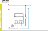
I see in the diagram you posted, you have the neutral and live going to A1 and A2, then the heating NO goes to 13 and then out on 14 to the white wire to fire the boiler. Is this correct?
I see in the diagram you posted, you have the neutral and live going to A1 and A2, then the heating NO goes to 13 and then out on 14 to the white wire to fire the boiler. Is this correct?
If you need to find a tradesperson to get your job done, please try our local search below,
or if you are doing it yourself you can find suppliers local to you.
Select the supplier or trade you require, enter your location to begin your search.
Please select a service and enter a location to continue...
Are you a trade or supplier? You can create your listing free at DIYnot Local