AC DC Adaptor fail

Sponsored Links
Is it normal to have an SMD connecting the 2 legs of a capacitor?
If the capacitor were a high voltage reservoir capacitor then yes. It would be a safety resistor, to drain off charge quickly after the power is switched off.
 
If the capacitor were a high voltage reservoir capacitor then yes. It would be a safety resistor, to drain off charge quickly after the power is switched off.
This is a cheap as it gets PSU. So, nothing fancy like that for it. But, the LED stays on after unplug. I imagine that does the draining.
 
the LED stays on after unplug. I imagine that does the draining
Yes, but it could also drain through these two resistors (R9 and 10 on the schematic), if the LED were to fail.

back.png
 
Sponsored Links
Impossible to identify this capacitor. It measures 1.45-1.48nF depending on probe polarity. So, I have to assume it's correct? The lossy image format used by this site losses some details from the original.
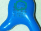
The markings are:
top: JNC
Bottom: 750
Above bottom: 400 or 40C

blue-capacitor.png
 
Last edited:
Impossible to identify this capacitor. It measures 1.45-1.48nF
That's the 'Class Y' capacitor.
It is used to limit RF interference.
It is designed to fail open circuit, ensuring isolation between the mains and ELV output, if it were to fail.
1.5nF is about right, a much larger value could cause a dangerous leakage current from the mains, bypassing the isolation.
blue-capacitor.png
The highlighted number will give you the intended value.
 
All the video instructions on shunt diagnosis are in non-english. I am guessing at what they are trying to do, and coming to the conclusion the shunt is gone.

With the multimeter set to auto ohms, the black probe connected to COM:

Black probe to pin1, red to pin2: 50+ mega ohms
Black probe to pin1, red to pin3: O.L/infinity - there is supposed to be a reading

Black probe to pin2, red to pin1: 50+ mega ohms
Black probe to pin2, red to pin3: O.L/infinity - there is supposed to be a reading

Black probe to pin3, red to pin1: 8+ mega ohms - there is not supposed to be a reading
Black probe to pin3, red to pin2: 5+ mega ohms - there is not supposed to be a reading

Now I need help finding a H431 BA substitute. The original part is not available.
 
Ordered 50x TL431A from china. Don't need that many. But, I will probably destroy some more while experimenting. All other components, excluding the IC's, checked out. I wonder what caused it to fail: bad luck or bad load?
 
My other adaptor had no problems with the load. The amperage simply dropped to a silly amount from the supposed 200mA to 50mA when the voltage was dragged down from from 18v to 13v. The other one is very likely structured differently and resembled the one described in the earlier video. It seems something worst is actually better depending on the application.

I'll call it quits if a replacement shunt also blows.
 
Out of curiosity, what controls the output voltage? Is there a single component that does it? I need a 21v power supply and got the 24v one because it was cheaper. I didn't think at low amperage of 200mA, a few volts difference is a big deal.

One solution I am thinking of is to output the DC to a discrete PWM controller. The PWM then feeds the end load. By reducing the PWM duty cycle, I will have a lower resulting voltage. This also lowers the load on the power supply.
 
Out of curiosity, what controls the output voltage?

I't done by feedback, using the opto-isolator. The brighter the opto, the higher the voltage on the output, so over a preset brightness level, the input is reduced. Find the potential divider network, adjust the values of those components, and you will adjust the voltage output.
The 20amp and bigger, extremely well built 50v, SMPSU's ex-BT telecomms, used to be very easy to change to 13.8v output, by simply changing a resistor value.
 
Find the potential divider network, adjust the values of those components, and you will adjust the voltage output.
Screenshot_20230226-133348_Chrome.jpg

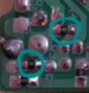
R9 and R10 are the potential divider,
(The tiny resistors on the bottom I highlighted earlier)
back.png
providing the reference for the shunt regulator IC3.
The 'error voltage' is modulated back through the opto-isolator to Pin 5 (feedback) of ME8115.
 
Is the feed back causing the problem? The PSU trying to maintain 24v output but the load doesn't allow it and permanently keeping the DC side 13.xV. The AC side compensates and keeps pumping in more until it blows?
 
Here's a description of a very similar power supply. My guess on how the feed back works turned out to be correct. Looks like this adaptor is not suitable for my application and will continue to blow. I am now hoping attaching a discrete PWM controller to the DC output will save the day.

I can now conclude the adaptor blowing is my own fault, and I will not give a bad review on the seller. I knew it was a gamble. This time I lost. Only If they had given me one of those adaptors that are said to be prone to start fires, it would have worked.

 
Last edited:

DIYnot Local

Staff member

If you need to find a tradesperson to get your job done, please try our local search below, or if you are doing it yourself you can find suppliers local to you.

Select the supplier or trade you require, enter your location to begin your search.


Are you a trade or supplier? You can create your listing free at DIYnot Local

 
Sponsored Links
Back
Top