Accenta 8 Mini alarm system - power failure & dead rkp

Joined
29 Aug 2008
Messages
31
Reaction score
0
Location
Cheshire
Country
United Kingdom
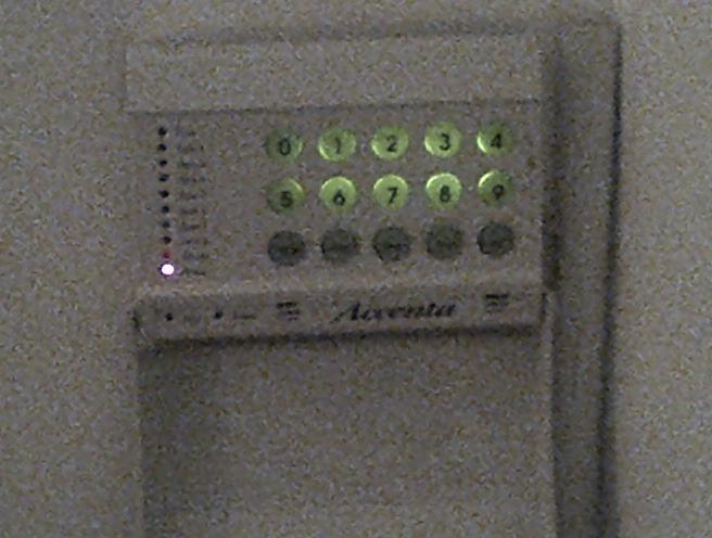
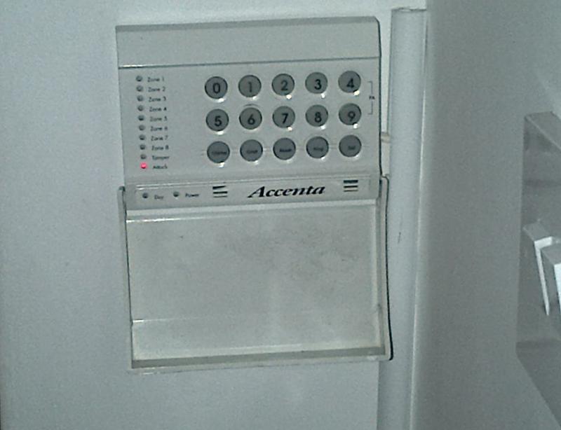
This morning our alarm system went off for no apparent reason and so I came downstairs to disarm it using remote keypad. However the rkp was completely dead, other than number keys illuminated. I also noticed that the internal sounder wasn't emitting its usual racket which I thought was rather odd. On checking the main consumer unit I noticed that the RCD for the protected circuits had tripped, not the MCB for the alarm control panel, so I reset it which stopped the bell ringing (peace and quiet, for a while!).

Time to open up the control panel and check the battery terminals etc.
Note: The battery was only replaced in July 2011 (Online 12v 2.2Ah).

On removing and then reconnecting the battery the bell box went berserk and so I went to the rkp to reset it but keypad was dead to all normal user codes and just squeaked like it was half dead.
With battery connected = inoperable squeaky remote keypad and loud alarm bell
Without battery connected = dead keypad and quieter bell

Checked battery with multimeter (not connected to panel) and reads 8v.

So I left the battery out and reset the the memory by wiring across terminals 19 and 27 to reset NVM which stopped alarm conditions and bell sounding, put back the control panel cover and started to think things through, which is why I'm now asking for some assistance.

Could a battery that's only 1.5 years old be faulty or am I into a bigger job? Any help really appreciated as well and truly broke after Christmas meaning hopefully another diy job.

P.S. I should also mention that I changed to a Texecom Odyssey bell box also 4 years ago as this was faulty due to corroded terminals. All has worked well since and no changes to any electrics on this circuit.
 
Sponsored Links
It sounds more like the power supply to the alarm has or is dying and not allowing enough power to the system. When you connect the battery it is increasing the system voltage but not enough as the battery has not been charging properly and is now almost flat.

Can you test the voltage on the panel at the "AUX 12V" terminals with your multimeter set to DC volts without the battery connected and see what the reading is please?
 
Can you test the voltage on the panel at the "AUX 12V" terminals with your multimeter set to DC volts without the battery connected and see what the reading is please?

Do you mean at the battery connection lead terminals (spade connectors) or on board itself?
 
Looking at a drawing of your control panel he means terminals marked as

+13v 0v Positioned just off centre

Don't forget the mains. Dangerous.
 
 
Sponsored Links
OK thanks. I will check this after I've disabled the bell box.
What's the simplest way to disable the siren and in what sequence, I forget stuff easily these days, as I'm getting older :)
 
If you mean the outside bell box then you can disconnect the wiring at the panel and it'll stop after 15 - 20 mins, otherwise you'll need to get up to it on ladders.
 
Thanks RF Lighting, I will hope for a dry day tomorrow and get the ladders out disable bell box outside.

BTW, Are you thinking that the transformer is knackered in the control panel?
I know the circuit powering the control panel is good as it also powers a power shower which is fine.
 
I'm thinking it's either the transformer which is not outputting the correct voltage, or there's some sort of high-ish resistance short on the outgoing wiring which is dragging the overall voltage down.

First thing to do is test the aux voltage at the panel, and then remove the aux power + and - wires. These wires power things like your PIR detectors.

See if the keypad comes back to life and the voltage at these terminals rises significantly.
 
OK understood, I will check it all out and report back, hopefully tomorrow
 
Checked battery with multimeter (not connected to panel) and reads 8v.

There's your problem! A battery only outputting 8 volts is going to drag the panel power supply down, which would explain why your keypad is unresponsive. Online are cheap and nasty batteries, I don't think I've seen any last more than 2 years so replace for a good quality type like Yuasa.

A power down and back up without re-connecting the faulty battery would have probably sorted the problem until you can source a replacement batt, no need to default the panel.

As for your external sounder, it has a very useful "engineer hold off" mode, which can be invoked from the panel. You'll need to refer to the instructions that came with it if you still have them or failing that, there will be a pdf of it on the net somewhere.

Thanks for your input here its much appreciated. I have a couple of questions as just about to disarm external sounder..
1. When I cleared the NVM and set to default conditions the RKP is still dead, this doesn't make sense does it, should it not be working according to your power down power back-up thinking?
2. If I open the panel front again surely this will cause external sounder to activate and not give me chance to follow instructions in the Texecom manual regarding connecting STRB wire to 0V terminal. Remenber that I can't set hold-off mode using RKP method.
3. Will the system function as normal without a battery fitted in the main panel? Or does the battery have to be in to power the RKP?
4. Why is Attack LED illuminated and all other keys dead even after reset to default by clearing NVM?
 
Assuming the panel is healthy then it will work without a battery, but it should show a power fault.

I missed that you have a texecom bell box. When you take the panel front off, you need to locate the wire which does the strobe.

Disconnect this wire and touch it on to the 0V terminal and then take it off, back on, back off, back on, back off till you've sent three 0V pulses to the bell box. It'll now be in hold off mode for 20 mins. If you remove power altogether it will stay in hold off mode until you re-apply power. Take a clear photo of the wiring before you disconnect anything so you can make sure you can reconnect it back up properly once the fault is resolved.
 
Thanks RF, I will try all in morning as dry day forecast (external sounder is over a pitched roof with no ladder access so one has to tread carefully, wet roof tiles don't help!
 
If putting it into hold off works then you won't need to get up to it, but I can't say for sure it will with your panel being a bit whacky at the moment! Fingers crossed!
 
Hello DDMA,

You've had some excellent replies from these engineers, I trust you are somewhere nearer a resolution now. If you are still deciding on your next move, perhaps if we look briefly at the whole situation in one 'fell sweep' then it may (or it may not, depends how you look at it) help toward a satisfactory conclusion:-

In one of your earlier posts you pointed out that the keypad 'squeaks' which would indicate that the keypad is working after a fashion.

A further post suggested that the keypad is part and parcel of the control panel, or words to that effect, and a clever little post that was, well done.

There is not a great deal you can do, if there is only one remote keypad and not another on board the panel or somewhere else. So the first thing to check is that you have a known working keypad. We need to check if there is a fuse on board the main pcb solely for the keypad, and also if there is a fuse inside the keypad itself. However, before we can go about changing fuses, the wiring to the keypad, if it has been disconnected must be connected again (colour for colour and with no wires touching each other), good connections are a must at this stage. Now we can go on to checking or rather replacing the fuse or fuses which 'protect the keypad' (although some would suggest the fuse or fuses are there to protect the panel, but that's for another day) preferably with 'new' and of the same rating, check the instructions for the fuse ratings.

So, although we don't yet know that the keypad is working correctly or not, we can leave that side of things and concentrate on the battery voltage and the reasons why the alarm is silenced with mains but not with battery:-

The fact that the keypad made a 'squeak' when the battery was connected tends to indicate that there was a certain amount of power left in the battery. Unfortunately, not enough. A low battery, particularly as low as 8 volts can cause all sorts of mysterious and wonderful problems, even to the extent of damaging the main pcb itself (the current limiting resistor is usually the first to go, but not always). But, we must ask ourselves, 'could a single powercut' reduce a battery from a steady 13.6 or 13.8 volts to a mere 8 volts in a single stroke. Well, it might be possible but I've never seen it. Mains voltage must be reaching the panel twenty four hours a day and seven days a week, every week in order to maintain the battery at the maker's working level (for want of a better term) and if a low battery of 8 volts is left inside the panel it will drag the current down, through the limiting resistor, and cause big problems. First things first then. Take out the battery and dispose of it properly, it's no good. gone, finished, dot.com and even if it's not, a brand new battery will give you that extra faith in resolving the problem.

Now you have no battery to power the system and the only other thing left is to rely on the mains electric supply. But is the electricity supply reaching the pcb inside the control panel. We need to be absolutely certain that it is (by the way, these questions have been answered in previous posts, we are simply going back through them). You have a multimeter and know how to use it. It stands to reason therefore that you know of the risks with 'mains electricity'. Mains enters the panel first from a fused spur situated near the panel, then on to a smaller fuse situated just before the transformer and then to the transformer 'primary winding'. You'll agree with that no doubt. Being careful to avoid any mains cable and the primary winding connections of the transformer, place your multimeter on the two terminals at the printed circuit board where the secondary windings of the transformer are connected, set the multimeter to above 20 volts AC before doing so and expect a value around say 15 to 17 volts AC. If you can not get a reading or the reading is below 12 volts then suspect the 'incoming mains and the transformer'. Of course, when doing this you need to ensure that the spur has a known good 2 or 3 amp fuse in it. If you have a good reading at this secondary connection there is no need to go any further with your 'mains' tests. If you don't have a good secondary, check the primary windings (Mains Voltage. take care !!) and expect 230 volts (change the setting on the multimeter). Check back to the fused spur at each junture and ensure that a mains voltage is reaching the panel.

When you are satisfied that each of these tests is in your favour, only then is it worth powering down the panel. Yes, the external sounder may well make a 'racket' when you open the panel, but your instruction manual should tell you how to enter engineering mode and silence the warning devices in a few seconds after the panel is opened. Take the advice offered in a previous post and place your meter on DC volts and check that you have a good 12 volts or more (sometimes 13.6 or so) DC at the 'auxillary terminal pair' (the pair you use to connect power for devices like passive infra red units), then expect about the same at the battery flying lead connection terminal pair on the pcb. As a final check, test for the same voltage at the ends of the flying leads themselves (the ones you connect to the battery). It is worth remembering that we can not even attempt to 'down power' 'remove and replace nvm's' or reprogram until we are absolutely sure that no physical faults exist in the system itself.

Take care, and let us know how you are getting on,

Chain Daisy.
 

DIYnot Local

Staff member

If you need to find a tradesperson to get your job done, please try our local search below, or if you are doing it yourself you can find suppliers local to you.

Select the supplier or trade you require, enter your location to begin your search.


Are you a trade or supplier? You can create your listing free at DIYnot Local

 
Sponsored Links
Back
Top