- Joined
- 27 Jan 2008
- Messages
- 29,045
- Reaction score
- 3,559
- Location
- Llanfair Caereinion, Nr Welshpool
- Country

I had something similar, also oil fired boiler, but in my case C Plan not Y Plan and with two pumps. How the original house owners used it I don't know, it was in a mess, had to go outside and down a set of steps and go into what was a garage and now a flat and plug in the pump. And it had at least 4 independent supplies.
So now all from one battery backed supply and added to motorised valves and relays to make it all controlled as it should be. I am using the T1 and T2 as that was the main reason for selecting Nest Gen 3, I have only two wires flat to main house, and they carry all the commands and power to the wall thermostat. I did consider a cradle, but how can one power the cradle during a power cut? The USB supply would need to be battery backed, which defeats the whole idea of having the system running from one single UPS supply.
What I may do is fit a second wireless thermostat in parallel placed in the living room, it would not matter if the batteries went flat as central heating will still work, and it will not matter if I light a fire in the grate as the hall one will still keep the system running, although the TRV's in the living room will stop living room being heated.
But either the thermostat needs to be total battery powered, or mains powered from same source as boiler, it will not work once the USB supply is lost, so the USB supply needs to come from the same FCU as the boiler, so may as well use the T1 and T2 options.
OK I have solar power, so even with a loss of grid power my freezers and central heating will still work, nothing else will work, but I have lived through the Winter of discontent and will never again rely on grid power for heating, once bitten twice shy.
I decided the only thing I could do was make out my own wiring diagram I still made an error, needs two relays really, but it works well enough. The oil boiler does not have a run on in my case, so has to use C or Y plan so thermo syphon can cool boiler into the DHW, no power to three port valve means it goes to DHW.
I sat there for ages tugging each wire to find out what each wire did, plus checking with meter. It is long winded, and clearly the installers could not be bothered, also the plumbing was up the creak, they clearly thought with two pumps they could control two zones, this did not work, when only one pump was running it forced water in reverse direction through the other pump, I have noted installers name, and this is on my black list of tradesmen I will never employ.
Although I can see where some wires go on your set up, I can't see where they all go, and to try and give you instructions put y with x may have some errors, hence answering in general terms.
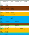
It seems you have 9 cables, left to right.
1) Black Motorised valve orange (switched live) (9), grey (hot water off), brown & white (heating on)(4) and blue (neutral).
2) White Programmer
3) White
4) White
5) White Programmer
Next group
6) White
7) White Thermostat Power
8) Gray
9) White Thermostat Switching
If you try to complete the labels likely you can find errors, you can't do it without making notes, that's how I did mine and I wrote numbers on each cable so I could reference them. When I did it we did not have solar panels and back up battery, so it would have been easy to use USB power from any socket, now glad I didn't.
So now all from one battery backed supply and added to motorised valves and relays to make it all controlled as it should be. I am using the T1 and T2 as that was the main reason for selecting Nest Gen 3, I have only two wires flat to main house, and they carry all the commands and power to the wall thermostat. I did consider a cradle, but how can one power the cradle during a power cut? The USB supply would need to be battery backed, which defeats the whole idea of having the system running from one single UPS supply.
What I may do is fit a second wireless thermostat in parallel placed in the living room, it would not matter if the batteries went flat as central heating will still work, and it will not matter if I light a fire in the grate as the hall one will still keep the system running, although the TRV's in the living room will stop living room being heated.
But either the thermostat needs to be total battery powered, or mains powered from same source as boiler, it will not work once the USB supply is lost, so the USB supply needs to come from the same FCU as the boiler, so may as well use the T1 and T2 options.
OK I have solar power, so even with a loss of grid power my freezers and central heating will still work, nothing else will work, but I have lived through the Winter of discontent and will never again rely on grid power for heating, once bitten twice shy.
I decided the only thing I could do was make out my own wiring diagram
I still made an error, needs two relays really, but it works well enough. The oil boiler does not have a run on in my case, so has to use C or Y plan so thermo syphon can cool boiler into the DHW, no power to three port valve means it goes to DHW.I sat there for ages tugging each wire to find out what each wire did, plus checking with meter. It is long winded, and clearly the installers could not be bothered, also the plumbing was up the creak, they clearly thought with two pumps they could control two zones, this did not work, when only one pump was running it forced water in reverse direction through the other pump, I have noted installers name, and this is on my black list of tradesmen I will never employ.
Although I can see where some wires go on your set up, I can't see where they all go, and to try and give you instructions put y with x may have some errors, hence answering in general terms.
It seems you have 9 cables, left to right.
1) Black Motorised valve orange (switched live) (9), grey (hot water off), brown & white (heating on)(4) and blue (neutral).
2) White Programmer
3) White
4) White
5) White Programmer
Next group
6) White
7) White Thermostat Power
8) Gray
9) White Thermostat Switching
If you try to complete the labels likely you can find errors, you can't do it without making notes, that's how I did mine and I wrote numbers on each cable so I could reference them. When I did it we did not have solar panels and back up battery, so it would have been easy to use USB power from any socket, now glad I didn't.
 .
.