badly designed tv/satellite faceplate?

Joined
3 Oct 2006
Messages
136
Reaction score
2
Location
Hampshire
Country
United Kingdom
Hi,

I have a few tv/satellite points going in, I ordered the faceplates to match our sockets and light switches, the sockets and light switches all fit fine, however I am struggling to fit the tv point.

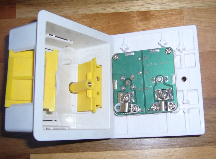
The clamp for the cable is right at the edge of the pcb with the connection for the signal wire further towards the middle, this means that from what I can tell I need to get the coax to do an immediate bend of at least 90deg - and it's quite thick stuff.. and the clamps aren't that strong so under too much pressure they will pop. I've wondered about trying to put a 'permanent' bend in the coax somehow.. heat, pliers..?

any hints? pic below:

oddTvPoint.jpg


thanks

Trev
 
Sponsored Links
Since there is no mains invovled and you are using a dryline box how about cutting away the bottom of the box. Then the cables can come straight out of the clamps and out of the bottom of the box.
 
I can do that in one location (not a bad idea), but the rest are metal boxes in brick/blockwork already plastered and painted..

any ideas for those locations - it's not just me then, they are an odd design?
 
They are a pretty poor design, however remember you only need to use the clamp to get a connection. It doesn't need to be overtight in order to give the cable strain relief.
 
Sponsored Links
Unfortunately, a lot of these sockets have this fundamental design flaw. You have very little choice other than to kink the coax, but it is detrimental to the signal quality.
 
thanks guys, will attempt to kink the coax and keep the clamp loose a bit to give some play..

was whinging about these connections to a guy at work and he suggested running the signal and shielding into chock block then running normal wire from the block to the face plate.. If I can't get them to work with a kink how bad would this be? Obviously every connection reduces signal quality and there would be a section of unshielded signal wire.. I just have no concept of what level of effect this would have.. (my boxes are 45mm so I would have room..)

cheers

Trev
 
was whinging about these connections to a guy at work and he suggested running the signal and shielding into chock block then running normal wire from the block to the face plate..
Trev

No, don't do this.....

Frank
 
Another option would be to forget the clamp alltogether, strip a length of outer sheath back, twist all the outer strands together and put into a piece of sleeve, put a ring crimp on the end of it and use the ring connector to connect to the gnd
 
but the rest are metal boxes in brick/blockwork already plastered and painted..
May not be a problem if you have a Dremel with a cut-off disk.
 
The MK ones are a bit better, as in position and termination point of cable

Here's a link, click on the internal picture

http://www.mk-shop.co.uk/products/S...t/4253114472?gclid=COzb9KL7yZYCFRpUEAodaGtoxg

they look like a much higher quality piece of kit.. might see if TLC will exchange.. (although can't find them with satellite connections)

Spark.. thanks, hadn't thought of that - sounds very workable, I might well give that a try if I can't source the above or they clash with the sockets etc..

cheers all - now have a few things to try!

Trev
 
I have to agree with you there Trev, it is a bad design flaw.

Obviously the person that designed the board did not get a bit of coax & play around with it & the enclosures etc.
 
co-ax sockets are universally crap for that reason, I'm afraid, athough with patience and care most can be fitted without kinking the cable, just a tight bend.

What I've done before now is leave a couple of inches inner insulation on, then take the cable in through the "wrong" side of the clamp, bending the inner core back over the clamp and into the centre contact. The one in your pic is particularly crap though, usually you've got a little more space between the clamp and the centre pin.
 
Another option would be to forget the clamp alltogether, strip a length of outer sheath back, twist all the outer strands together and put into a piece of sleeve, put a ring crimp on the end of it and use the ring connector to connect to the gnd

We used to terminate some cables by inserting a paper sleeve under the braiding (to protect the dielectric), wrapping a couple of turns of wire round the braid, and soldering it. A rubber or heatshrink sleeve over the lot finished off the cable end, leaving two wires to solder to a printed circuit board.
 

DIYnot Local

Staff member

If you need to find a tradesperson to get your job done, please try our local search below, or if you are doing it yourself you can find suppliers local to you.

Select the supplier or trade you require, enter your location to begin your search.


Are you a trade or supplier? You can create your listing free at DIYnot Local

 
Sponsored Links
Back
Top